
Open a 5 kW string inverter and you will not find a mysterious black box. You will find a chain of power electronics blocks, each with one job. Solar power enters as variable DC from the panel strings and leaves as grid-synchronised AC at 230 V (single-phase) or 415 V (three-phase) and 50 Hz. A solar inverter circuit diagram is the map of that journey.
Most explanations stop at “it converts DC to AC”. That is true and not much use when you want to read a datasheet, size strings, or work out why a unit trips at 2 pm in May. This guide goes one level deeper. It walks through the power path of a modern transformerless string inverter: the DC input and EMC stage, the MPPT boost converter, the DC link, the IGBT bridge, and the output filter, grid relay and control board. For each block it says what the block does, which components you would see on the schematic, and where problems usually start. It also shows how a hybrid inverter’s circuit differs from an on-grid one.
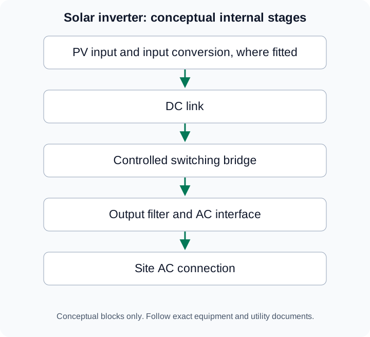
Short version. Inside a string inverter the order is fixed: DC input and sensing, MPPT boost converter, DC link capacitor, IGBT bridge, output filter, grid relay. The control board watches every stage and can open the grid relay at any moment. Numeric settings such as voltage windows, trip limits and switching frequency belong to the exact model, so read them from its manual.
Two drawings share this name: system single line diagram vs internal circuit
When an installer or DISCOM engineer says “circuit diagram”, they usually mean the system single line diagram (SLD): the one-line path from array to meter. When an engineer or student says it, they mean the power electronics inside the inverter. This page is about the second one. The first has its own guides.
| System single line diagram | Internal inverter circuit | |
|---|---|---|
| What it shows | Array, combiner or string fuses, DC isolator, DC surge protection, inverter, AC isolator, distribution board protection, AC surge protection, net meter, grid connection, earthing | Input stage, MPPT boost, DC link, switching bridge, filter, relay, control board |
| Who uses it | Installer, DISCOM, electrical inspector | Designer, service engineer, student |
| Where to find it | Single line diagram glossary entry and the wiring diagram guide | This page |
| What it cannot do | Explain why the inverter trips | Help you wire a roof or apply for net metering |
For the physical layout of a rooftop connection, with cable sizes, isolator positions and earthing, use the solar inverter wiring diagram guide. For a hybrid system with a battery, see the inverter and battery connection diagram.
How to read an inverter circuit diagram
A solar inverter circuit diagram is a block diagram at heart. Even a detailed manufacturer schematic groups into the same functional blocks, connected in one direction of power flow. By convention DC enters from the left and AC leaves to the right. High-power semiconductors (the boost switches and the bridge IGBTs) sit on a shared heatsink. The control board draws thin signal lines to every block, carrying sensor readings in and gate-drive pulses out.
Three symbol families do most of the work:
- Semiconductors. IGBTs and MOSFETs drawn as switches, with diodes for freewheeling and rectification.
- Passives. Inductors for the boost stage and output filter, capacitors for the DC link and EMC suppression.
- Protection and switching. Fuses, surge protection devices (SPDs), relays and current sensors.
Read the diagram as a list of constraints, not as a picture of a machine. Every box tells you something the installer must respect: a maximum voltage, a current limit, a protection that will open the circuit.
The full block diagram
This is the power path of a typical single-phase transformerless string inverter, the architecture behind most residential on-grid units. Voltages and frequencies inside the box vary by design, so none are drawn here.
 PV String 1 ----> [DC Input / EMC Filter] --> [MPPT Boost 1] --+
 PV String 2 ----> [DC Input / EMC Filter] --> [MPPT Boost 2] --+
                                                                 |
                                                         [DC LINK capacitors]
                                                                 |
                                                   [IGBT bridge, PWM switching]
                                                                 |
                                                         [Output filter (L / LCL)]
                                                                 |
                                               [Grid relay + AC sensing] ----> AC terminals

      [Control board]  ==  gate drives, sensors, MPPT loops, grid sync, protection logic
Two strings enter on the left, each with its own input conditioning and boost stage. That is what “dual MPPT” means physically: two independent boost converters feeding one DC link. A single-MPPT unit has one input chain. The difference between string voltage and MPPT voltage becomes obvious once you see where each voltage lives in the chain.
Block 1: DC input and EMC filter
The first block conditions the raw power from the roof. It has three jobs: protect, filter and measure.
Protect. Depending on the model, each string input can have reverse-polarity protection, fuses, and surge protection devices (SPDs). An SPD clamps lightning-induced and switching transients before they reach the semiconductors. It is a sacrificial part: after a nearby strike, a failed SPD has done its job and needs replacing. The SPD glossary entry explains the types.
Filter. Common-mode chokes and X/Y capacitors form the electromagnetic compatibility (EMC) filter. It works in both directions: it keeps the inverter’s own switching noise from travelling up the DC cables, and it keeps cable-borne noise away from the control electronics.
Measure. Voltage and current sensors read each input. A residual current monitoring unit (RCMU) watches for leakage to earth, and an insulation resistance check runs before the inverter connects. In a transformerless design these functions replace the isolation an old transformer provided, as covered in the transformerless vs transformer inverter comparison.
Block 2: MPPT boost converter
This is where the solar-specific intelligence lives. The boost converter, built from an inductor, a fast switch and a diode, does two jobs at once.
Voltage conversion. The bridge needs a DC link voltage higher than the peak of the AC waveform it produces. A string’s voltage swings with temperature and sunlight, so the boost stage lifts whatever the string delivers to the level the link needs.
Maximum power point tracking. The control board changes the switch duty cycle many times a second. Each change alters the voltage the string is held at, and the algorithm hunts for the point where voltage times current is highest. The inverter MPPT guide explains the algorithms. Here the point is the hardware that executes them.
Each MPPT input is a full boost circuit. That is why shading one string of a dual-MPPT inverter does not pull down the other: the two stages hold their strings at separate operating points. Dual vs single MPPT covers when that matters. Qbits publishes single-phase on-grid models from single-MPPT units up to the dual-MPPT QB 4/5/6 KTLD, which has an 80 V to 550 V MPPT window and 20 A input per MPPT, according to the Qbits product specification. The QB 4.2/4.6/5/5.4/6KTLS is a single-MPPT model with a 40 V to 600 V MPPT window.
This block runs hot. The boost switch and inductor carry full string power continuously, which is why they bolt directly to the heatsink.
Block 3: DC link
Between the boost stage and the bridge sits the DC link, a bank of capacitors holding the intermediate DC voltage. It looks passive on the diagram. It is not.
The DC link is an energy buffer. Solar input changes slowly with clouds and temperature. The bridge, by contrast, draws power in pulses. In a single-phase inverter, AC power pulsates at twice the line frequency, which is 100 Hz on a 50 Hz grid, so the capacitor bank charges and discharges every 10 milliseconds. A three-phase stage delivers near-constant power, which is one reason three-phase designs need proportionally less link capacitance.
Capacitor choice is a reliability decision. Aluminium electrolytic capacitors are compact and economical but age with heat. A common design rule of thumb is that electrolytic capacitor life roughly halves for every 10 degrees Celsius of additional operating temperature, so a hot enclosure shortens it. Film capacitors cost more and tolerate heat better. Too little link capacitance increases voltage ripple, which stresses the bridge devices and distorts the output current.
The link also stores hazardous energy after shutdown. That is a main reason the enclosure stays closed for anyone but trained service staff.
Block 4: IGBT bridge
This is the block that actually makes AC. In a single-phase inverter, four insulated-gate bipolar transistors (IGBTs) sit in two legs, with a diode across each switch to carry current during freewheeling intervals. A three-phase inverter uses three legs, one per phase.
The control board drives the gates with pulse width modulation (PWM). The bridge output is a high-frequency pulse train whose pulse widths vary sinusoidally, so its local average traces a 50 Hz sine. That raw waveform goes to the output filter. The switching frequency is a design choice and differs between models.
Two design choices define this stage:
- Switch technology. Silicon IGBTs are common in string inverters. Silicon carbide MOSFETs switch faster with lower losses and appear in some newer designs.
- Topology. A plain H-bridge with bipolar PWM creates leakage-current problems on a floating array. Transformerless designs commonly use variants such as H5 or HERIC, which add a switch or path that disconnects the DC side from the AC side during freewheeling and so limits the common-mode voltage swing on the array.
The bridge devices are among the most heavily stressed semiconductors in the machine: they switch full power thousands of times a second, and heatsink temperatures rise in an Indian summer. That is why thermal design and derating behaviour matter so much, as the inverter overheating guide explains.
Block 5: output filter, grid relay and control board
The last stretch turns a PWM waveform into grid-quality electricity and connects it safely.
Output filter. Inductors, or an inductor-capacitor-inductor (LCL) network, between the bridge and the AC terminals remove the switching-frequency content. What remains is a near-sinusoidal current. Grid standards limit the harmonic distortion of injected current, for example IEC 61727 for utility-interconnected PV systems, and the filter is what keeps the harmonics inside that limit.
Grid relay. A relay (commonly two in series, so that a single welded contact cannot defeat disconnection) joins the filtered output to the AC terminals. The inverter checks the relays at start-up. It closes them only after grid voltage and frequency are inside the permitted window and synchronisation is established. When the grid fails, the relays open within a short time set by the standard. That is anti-islanding protection carried out by this exact hardware, and the anti-islanding glossary entry covers the logic.
AC sensing. Voltage and current sensors at the AC side measure exported energy and close the control loops. The generation figure in a monitoring app originates here.
Control board. A digital signal processor runs the machine: MPPT loops, PWM generation, grid synchronisation with a phase-locked loop, protection logic and communications. Gate-driver circuits translate its logic-level signals into the higher-voltage pulses that switch the IGBTs. When any sensor reports an out-of-range value, this board raises the fault message you see on the display.
| Block | Key components | What goes in | What comes out | Primary job |
|---|---|---|---|---|
| 1. DC input / EMC | Fuses, SPDs, chokes, RCMU, sensors | String DC | Conditioned DC | Protect, filter, measure |
| 2. MPPT boost | Inductor, switch, diode | Variable DC | Regulated higher DC | Track the maximum power point, lift voltage |
| 3. DC link | Electrolytic or film capacitors | Boosted DC | Stable DC bus | Buffer and smooth |
| 4. IGBT bridge | IGBTs and diodes | DC bus | PWM waveform | Create the AC shape |
| 5a. Output filter | Inductors, capacitors | PWM waveform | Sine-wave current | Remove switching ripple |
| 5b. Grid relay | Series relays, sensors | Filtered AC | Grid connection | Safe, synchronised connection |
| 5c. Control board | DSP, gate drivers | Sensor signals | Gate pulses, fault flags | Supervise everything |
On-grid vs hybrid: how the circuit diagram changes
A hybrid inverter contains every block above, plus three additions. They are hardware, not firmware, which is why an on-grid unit cannot be upgraded to hybrid in place.
Addition 1: a bidirectional battery DC-DC converter. This stage connects the battery to the DC link. It runs as a buck converter when charging the battery from the link and as a boost converter when discharging the battery into it, with its own inductor, switches and current sensors. The Qbits QBH hybrid models list battery current ratings that vary by model, according to the Qbits product specification, and the product data says lead-acid or lithium use is subject to compatibility.
Addition 2: a backup output path. A second AC output feeds selected loads during an outage. A transfer arrangement separates that output from the grid side when the grid fails, so backed-up circuits stay live while the grid terminals open. How long the changeover takes is a model-specific figure, so read it from the datasheet of the exact model.
Addition 3: a heavier control board. The hybrid controller must exchange data with the battery management system, run charge and discharge schedules, and change its behaviour between grid-following and islanded operation, where the inverter itself sets the voltage and frequency reference.
The on-grid vs hybrid guide covers the purchase decision. The circuit point is simpler: a hybrid is an on-grid inverter with a second DC-DC stage and a second relay path. Compare the two ranges on the on-grid inverter and hybrid inverter pages.
Common failure points, block by block
Every block has a characteristic failure signature. Knowing the map turns a vague fault message into a short list of suspects. The solar inverter troubleshooting guide covers the symptom side. This table covers the circuit side, and it describes tendencies, not failure rates.
| Block | Common failure | Typical symptom | Usual contributing cause |
|---|---|---|---|
| DC input / EMC | Failed SPD or fuse | No generation after a storm | Lightning or switching surge |
| MPPT boost | Switch or inductor stress | Repeated DC input overcurrent faults | Thermal stress, wiring faults |
| DC link | Aged electrolytic capacitors | Bus voltage faults on hot afternoons | Heat ageing over years |
| IGBT bridge | Device or gate-drive failure | Sudden shutdown, internal fault message | Thermal cycling, overstress |
| Output filter | Degraded filter component | High distortion or grid trips | Overstress, ageing |
| Grid relay | Worn or stuck contacts | Relay check failure at start-up | Repeated switching under load |
| Control board | Auxiliary supply failure | Dead display, no start | Surge entering through AC side |
| Cooling | Fan or heatsink blockage | Output limited at midday | Dust, heat, age |
Three patterns stand out:
- Heat is the master variable. Capacitors, IGBTs and fans all age faster in hot enclosures. A unit mounted shaded and with clear airflow is in a better position than an identical one on a sun-baked west wall.
- Storm damage enters through the cables. The DC input stage absorbs whatever the roof wiring collects, and the AC side takes what the grid sends.
- Start-up self-tests catch a lot. Relay checks and insulation checks at dawn find hardware problems before the power stage energises. An inverter that refuses to start is often protecting itself correctly.
For a message-to-cause walkthrough, see the solar inverter error codes guide. Repair is not a DIY job: the fault list above is for talking to your installer or service channel, not for opening the unit.
Transformer versus transformerless topology, and the isolation consequence
This is the biggest branch in inverter topology, and the consequence is isolation, not efficiency. A transformer puts a magnetic barrier between array and grid, so no conductive path exists between them. A transformerless inverter removes that barrier, which changes what the protection circuits must do.
| Aspect | With transformer | Transformerless |
|---|---|---|
| Galvanic isolation | Present | Absent |
| Weight and volume | Higher | Lower |
| Conversion losses | Extra magnetic and copper loss | No transformer loss |
| Earth fault method | Ground fault interrupter workable | Residual current monitoring per IEC 62109-2 |
| Array earthing | One pole earthed in some designs | Array floats relative to earth |
| Leakage sensitivity | Lower | Sensitive to module capacitance and damp |
The trade-off is often framed as efficiency against safety. That framing is wrong. A transformerless design is not less safe. It is differently protected, with the magnetic barrier replaced by continuous monitoring of insulation resistance and residual current. What suffers is tolerance for poor installation. Wet conduit or a badly bonded frame produces leakage that a transformerless inverter detects and refuses to start against. An isolated design may run straight through the same defect. The fault is real in both cases. Only one topology tells you.
Single-phase and three-phase output stages are not the same circuit
The output stage changes with phase configuration, and so does the waveform. A single-phase inverter feeds one live conductor and neutral. A three-phase inverter feeds three live conductors 120 degrees apart. Device count, DC link stress and filter design all follow from that.
| Parameter | Single-phase stage | Three-phase stage |
|---|---|---|
| Bridge arrangement | H-bridge, two legs | Three legs, one per phase |
| Controlled switches, two-level | 4 | 6 |
| Instantaneous output power | Pulsates at twice line frequency | Constant across three phases |
| DC link capacitance | Larger, to absorb the pulsation | Smaller for the same rating |
| Typical service | Residential | Commercial and industrial |
The DC link row is the one designers care about. Single-phase power pulsates, so the capacitor bank has to ride through every half cycle. The phase comparison guide covers selection. Qbits publishes single-phase on-grid models in the TLS and TLD series and three-phase models in the TLC series, listed on the on-grid inverter page.
The protection circuits and the fault each one catches
Protection is where a block diagram earns its keep during troubleshooting. Each function watches one class of fault and has one action available: open the grid relay, or refuse to close it.
| Protection function | What it detects | Governing document |
|---|---|---|
| Anti-islanding | Grid supply lost while exporting | IEC 62116, in India IS 16169 |
| Insulation resistance check | Low array-to-earth resistance | IEC 62109-1 and 62109-2, in India IS 16221 (Part 2) |
| Residual current monitoring | Standing and step residual current | IEC 62109-2 |
| Over and under voltage trip | Grid voltage outside the window | CEA connectivity regulations, DISCOM conditions |
| Over and under frequency trip | Grid frequency outside the window | CEA connectivity regulations, DISCOM conditions |
| DC injection limit | DC component in the AC output | CEA connectivity regulations |
| Surge protection | Lightning and switching transients | IEC 62109-1, wiring codes |
| Over temperature derating | Heatsink and ambient temperature | Model specification |
Anti-islanding carries the life-safety purpose. If DISCOM supply disappears while a lineman is working, an inverter that keeps energising the feeder creates an unexpected live circuit. Residual current monitoring surprises installers: IEC 62109-2 requires the unit to react to sudden step increases in residual current, not only a standing value. A marginal earth fault can therefore pass a start-up check and trip hours later when humidity rises. The ground fault guide sets out the diagnostic sequence.
Why Indian grid conditions drive the protection settings
The circuit is the same worldwide. The settings are not. The trip windows, and the ride-through behaviour between them, have to match the local grid code and the DISCOM’s connection conditions. In India the national reference is the Central Electricity Authority’s technical standards for connectivity of distributed generation resources, which the solar inverter regulations guide covers alongside the BIS and IEC standards. The DISCOM’s conditions and the model manual are the other valid sources for a setting.
The hardware side shows up in a published specification. The Qbits QB 4.2/4.6/5/5.4/6KTLS single-phase family lists a 90 Vac to 290 Vac adjustable grid range, according to the Qbits product specification. The acceptance window is a firmware parameter, not a fixed circuit property. Two rules follow.
- A wide adjustable range is a capability, not a licence. The commissioned setting must stay inside what the CEA regulation and the DISCOM allow.
- Widening a trip window to stop nuisance tripping hides the cause. Repeated noon overvoltage trips usually mean a weak feeder, a long AC cable or a loose connection.
The India grid tuning guide works through that diagnosis. The TLS, TLD and TLC on-grid series are specified as IP66 enclosures, according to the Qbits product specification.
Worked example: turning datasheet limits into a string count
This uses published inverter limits and assumed module parameters. It is arithmetic, not field data. Substitute real module values before designing anything.
Inverter limits. QB 4/5/6 KTLD, single-phase on-grid, dual-MPPT. MPPT window 80 V to 550 V, 550 V maximum DC, 20 A input per MPPT, according to the Qbits product specification.
Assumed module, for illustration only. Open circuit voltage at standard test conditions 41.5 V. Temperature coefficient of open circuit voltage minus 0.27% per degree Celsius. Short circuit current 13.8 A.
Step 1. Correct open circuit voltage to the coldest expected cell temperature. Standard test conditions define cell temperature as 25 degrees Celsius. Take a coldest expected cell temperature of 0 degrees Celsius, a drop of 25 degrees.
Voltage rise = 25 × 0.27% = 6.75%
Corrected open circuit voltage = 41.5 × 1.0675 = 44.3 V per module
Step 2. Divide by the maximum DC voltage.
550 ÷ 44.3 = 12.4 modules
Round down. Maximum series count is 12 modules. Rounding up to 13 gives 576 V, which breaches the 550 V limit on a cold morning and can damage the input stage.
Step 3. Check the tracking floor when hot. String voltage falls as cells heat up. A 12 module string clears the 80 V floor easily at peak summer cell temperature. On very short strings this check binds first.
Step 4. Check current per MPPT input. One string at 13.8 A short circuit current sits under the 20 A limit. Two strings in parallel on one input give 27.6 A, which exceeds it. So this model takes one string per MPPT with this module, giving two strings, not four.
Six misreadings that cause real wiring errors
Most circuit diagram mistakes are not arithmetic. They are misreadings of what a symbol promises.
- Treating the tracking window as the voltage limit. Size against the damage threshold on the coldest morning, then check normal operation sits inside the tracking window.
- Reading MPPT count as string capacity. Two inputs do not mean four strings. Maximum input current per MPPT decides that.
- Assuming the diagram supplies the protection it draws. Isolators, surge devices, fuses and earthing are often site-supplied items drawn for completeness.
- Putting surge protection on the wrong side of an isolator. A device that disconnects when the isolator opens protects nothing during maintenance.
- Treating a nameplate rating as continuous output. Output derates with heatsink temperature, and clipping limits the AC side when the array is oversized. Both are normal.
- Assuming any internal diagram is a service schematic. It has no component values, no test points and no discharge sequence.
A myth worth correcting on top of these: that a current-generation residential inverter shows a large 50 Hz transformer on its schematic. Most are transformerless, so a schematic with a large transformer is either an older design or a different class of machine. Another: that more blocks mean more failure risk. A hybrid has more blocks, but risk follows thermal design and component quality, not block count. The real cost of each extra conversion stage is a small loss of efficiency on that path, which is why round-trip efficiency through a battery is lower than the grid-tied path.
The bottom line
A solar inverter circuit diagram, read at the level of the inverter itself, is a chain of blocks. Power moves through DC input and EMC filtering, MPPT boost conversion, the DC link and the IGBT bridge. Then it passes the output filter, grid relay and control board. The relay releases power to the grid only when every check passes. Once you hold that map, datasheets become readable, fault messages become diagnosable, and the on-grid versus hybrid question reduces to a second DC-DC stage and a second relay path.
Qbits inverters for this guide
Specs below come from each model's datasheet. Confirm the exact model and current written terms with Qbits before you buy.
QB 1.5/2.0/2.7/3.0/3.3/3.6/4.0KTLS
- Power
- 1.5–4 kW
- Phase
- Single-phase
- MPPT
- Single-MPPT
QB 4.2/4.6/5/5.4/6KTLS
- Power
- 4.2–6 kW
- Phase
- Single-phase
- MPPT
- Single-MPPT
QB 5/6/8/10/12/15/17KTLC
- Power
- 5–17 kW
- Phase
- Three-phase
- MPPT
- Dual-MPPT
Frequently Asked Questions
Is a solar inverter circuit diagram the same as a home solar wiring diagram?
What order do the blocks go in inside a string inverter?
What does the MPPT circuit actually do in the diagram?
Does a transformerless inverter still have ground fault protection?
How many switching devices does a three-phase inverter stage need?
Can I repair an inverter using a circuit diagram from the internet?
Which standards govern the protection circuits drawn in the diagram?
Does the number of MPPTs tell me how many strings I can connect?

Keyur Rakholiya CTO, Qbits Energy
Listed by Qbits as its CTO. Current role, technical responsibilities and credentials require confirmation by the company owner.