
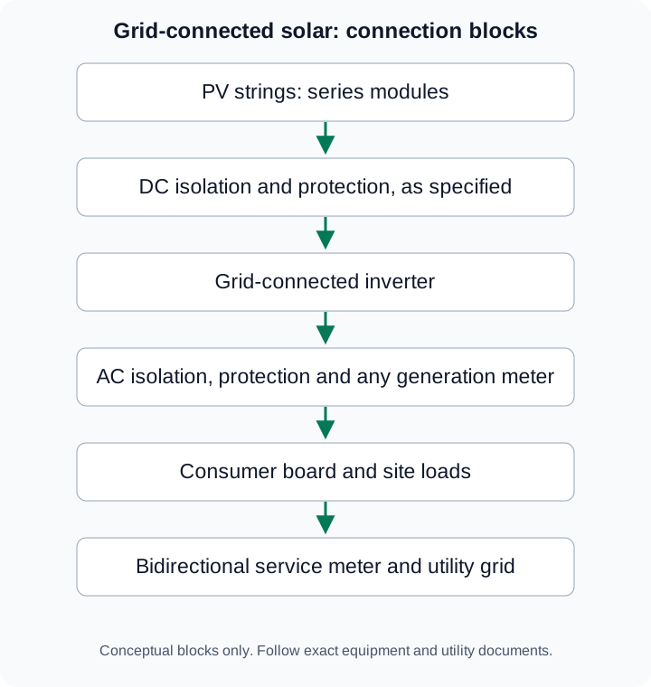
A solar inverter wiring diagram is four diagrams stacked together. The DC run from the array. The inverter terminal layout. The AC run to your distribution board. And the earthing that ties every metal part to one point. Add the utility metering and you have the complete circuit.
Most diagrams online draw the boxes and skip the parts that fail. Connector crimps. Isolator ratings. Residual-current device type. Torque on a DC terminal.
This guide covers an on-grid system from the panels to the meter and the grid. If your system has a battery, wire the battery side from the inverter and battery connection diagram as well. This guide walks the run in order, from the first connector pair on the roof to the meter at your service entrance: a numbered procedure, a worked cable-sizing calculation, single-phase versus three-phase neutral handling, the tests that happen before energising, and the errors that cause the most callbacks.
One condition applies throughout. This work must be carried out by a qualified, licensed electrician. The installation manual for your exact model and your local wiring rules take precedence over anything here. In India that means the Central Electricity Authority (Measures relating to Safety and Electric Supply) Regulations, 2023, IS 732:2019, and your DISCOM connection conditions. Where this page and your manual disagree, the manual wins.
Short version. A solar inverter wiring diagram runs in one direction. PV strings feed a DC surge protection device and a DC isolator, then the inverter. The output passes an AC isolator and a correctly rated breaker with the right residual-current device, then a generation meter where the DISCOM requires one, then the consumer board, then the bidirectional net meter and the grid. Every metal part shares one earth.
The complete wiring run, in order
Read the system as a single line from the roof to the street. Each stage has one job, one protective device, and one place it can be isolated. Order matters more than any individual component, because a device fitted on the wrong side of a junction protects nothing.
| Stage | Component | Sized against |
|---|---|---|
| 1 | PV modules in series | Module Voc at lowest site temperature |
| 2 | Connectors and DC cable | Isc, run length, voltage-drop target |
| 3 | DC surge protection device | Array voltage class and exposure |
| 4 | String fuses, where required | Module maximum series fuse rating |
| 5 | DC isolator | Array Voc and 1.25 times Isc, DC-rated |
| 6 | Inverter DC input | MPPT window and per-input current limit |
| 7 | AC isolator | Inverter maximum continuous AC current |
| 8 | AC breaker and RCD | 1.25 times inverter AC output current |
| 9 | Generation meter, where required | DISCOM specification |
| 10 | Consumer distribution board | Board rating and a spare way |
| 11 | Bidirectional net meter | DISCOM specification |
The installation sequence follows from that order.
- Check the string, cable and protective-device schedules against the inverter datasheet.
- Mount the inverter to the clearances in the manual, out of afternoon sun.
- Run DC cable in UV-resistant conduit, with every roof penetration sealed.
- Crimp connectors with the matched die, one brand throughout, then tug-test each joint.
- Bond module frames and mounting structure to the earthing system first.
- Land DC conductors on the isolator and surge device, polarity marked at both ends.
- Verify polarity and open-circuit voltage at the inverter end, isolator open.
- Connect DC into the inverter, respecting maximum input current per MPPT.
- Run AC cable to the AC isolator, then to the breaker and RCD in the board.
- Complete earthing and bonding, and measure continuity end to end.
- Label every isolator, breaker and meter, and fix the shutdown placard.
- Run the commissioning tests, record them, then energise in the manual’s sequence.
DC side: strings, polarity, connectors and isolation
The DC side carries the highest voltage in a residential system and the least forgiving current.
Every DC decision starts from two module figures: open-circuit voltage at the coldest expected temperature, and short-circuit current.
String polarity is checked with a meter at the inverter end before the conductors go near the inverter. A reversed pair often reads zero rather than flagging itself, and the installer starts hunting a phantom module fault.
Use one manufacturer of MC4-style connector throughout, with the matching crimp die. Cross-mated pairs from two brands seat correctly and look identical, but the contact geometry differs enough to raise resistance. Never disconnect a PV connector under load.
The DC isolator must be DC-rated, not an AC switch pressed into service. It needs a voltage rating above array Voc at the lowest site temperature, a current rating at or above 1.25 times array Isc, both poles broken, and a position within reach of the inverter.
String fuses are a design decision, not a default. With one or two strings on an input, no fault combination can push reverse current past a module rating. At three or more parallel strings they become necessary, rated above string operating current and below the module maximum series fuse rating. The string sizing and overcurrent protection guide covers the arithmetic, and the string sizing calculator screens the series count.
A surge protection device belongs within about 10 metres of the inverter DC input; beyond that, fit a second at the array end. Array earthing is separate: frames and rails bond to the main earth, which gives earth-fault detection a reference.
Respect the published per-input limits. Qbits lists 20 A maximum DC input current per MPPT on the single-phase TLS and TLD on-grid models, and 180 V to 1000 V MPPT with 1100 V maximum DC for the 6 to 17 kW three-phase TLC family, according to the Qbits product specification. Other families list different windows, so use the numbers for your exact model and download the model datasheet before the design is frozen.
Worked example: sizing the DC cable to a voltage-drop limit
Cable size has two tests. First, current-carrying capacity under real conditions, including conduit grouping and ambient temperature. Second, voltage drop. Passing the first and failing the second gives a system that is safe and quietly lossy for its whole life.
For a two-wire DC run:
L is the one-way run in metres, I is operating current in amperes, ρ is resistivity in ohm sq mm per metre, and A is cross-section in sq mm. Copper sits near 0.0172 at 20 degrees C, but a rooftop conduit runs hot, so this example uses 0.022.
Worked example inputs. One string, single-phase system. Maximum-power current 11 A, maximum-power voltage 380 V, one-way run 25 m, copper, 4 sq mm.
| Step | Calculation | Result |
|---|---|---|
| Loop length | 2 × 25 m | 50 m |
| Numerator | 50 × 11 × 0.022 | 12.1 |
| Voltage drop | 12.1 / 4 | 3.03 V |
| As a percentage | 3.03 / 380 | 0.80% |
| Power lost | 0.80% of 4,180 W | about 33 W |
At 4 sq mm the drop is 0.80%, inside the 1% designers usually target on a DC run and well inside the general limits IS 732:2019 sets for an installation. Step to 6 sq mm and the same run falls to 2.02 V, or 0.53%, which buys roughly 11 W at full output. A design sheet should show that tradeoff, not hide it.
The AC side uses the same formula with the AC current. A 5 kW inverter at 230 V draws about 21.7 A; over 12 m in 6 sq mm that gives 1.91 V, or 0.83%. For three-phase the multiplier changes from 2 to the square root of 3, because the return path is shared.
AC side: isolator, breaker rating, RCD type and the board
The AC side is where a rooftop system meets an installation that was never designed for a second source. Three components decide how that goes: a dedicated AC isolator, a breaker sized against the inverter rather than the load, and the correct type of residual-current device.
Size the breaker at about 1.25 times the inverter maximum continuous AC output current, rounded up to the next standard rating. A 5 kW single-phase inverter at roughly 22.7 A gives 28.4 A, which lands on a 32 A miniature circuit breaker. The cable feeding it must carry at least the breaker rating under its installation conditions.
A transformerless inverter has no galvanic isolation between array and grid, so an earth fault can produce residual current with a smooth DC component. That decides the RCD type.
| RCD type | Detects | Use on a solar AC circuit |
|---|---|---|
| Type AC | Sinusoidal AC residual current only | Never acceptable |
| Type A | AC plus pulsating DC residual current | Acceptable where the manual says so, typically when the inverter has integrated DC residual-current monitoring tested to IS/IEC 62109-2 |
| Type B | AC, pulsating DC and smooth DC residual current | Required where the inverter has no integrated DC fault-current detection, or where the manual specifies it |
The AC isolator belongs next to the inverter, lockable, and the final connection should use a dedicated way in the board.
Earthing and equipotential bonding
Earthing does two jobs. It gives fault current a low-impedance path back to the source so protective devices operate. And it holds every exposed metal part at the same potential, so nobody takes a shock from touching two things at once. That covers frames, rails, the inverter enclosure, isolator enclosures and metal conduit.
The rule people skip is the important one. There is one earthing system, not two. A separate earth pit for the array, unbonded to the building main earthing terminal, creates a potential difference that discharges through whatever bridges the two systems.
- Bond module frames to the rails, and the rails through to the main earth, at the specified size.
- Bond to clean, un-anodised metal with a washer that bites through the coating. An anodised frame is an insulator on its surface.
- Run a continuous protective conductor from the inverter earth terminal to the board, not to a local rod.
- Bond any building lightning protection system to the same main earthing terminal.
- Measure and record earth continuity at commissioning rather than assuming it.
On a transformerless inverter the array is not galvanically separated from the grid, so functional earthing of a live PV conductor is generally not permitted. The solar inverter grounding guide covers the measurement method.
Where the generation meter and net meter sit
Metering position is set by the DISCOM, so getting it wrong means a failed inspection rather than a technical fault. Requirements vary by state and by DISCOM, and the threshold for a separate generation meter is not uniform.
The bidirectional net meter replaces the existing service meter at the service entrance, upstream of the whole installation including the point where the solar circuit joins the consumer board. That is what lets it record import and export separately on one connection.
The generation meter, where a state requires one, sits between the inverter AC isolator and the consumer board. Being on the PV branch only, it records gross PV output regardless of how much the premises consumed.
A current transformer for export control goes on the incoming supply conductor, on the grid side of the PV connection point, so it sees net flow. On the load side, or reversed, the control logic reads the wrong sign. The net metering application guide covers the approval sequence.
Single-phase versus three-phase wiring, and the neutral
The DC side of a single-phase and a three-phase system looks nearly identical. The AC side does not. Three things change the drawing: conductor count, neutral handling and phase rotation.
| Item | Single-phase | Three-phase |
|---|---|---|
| AC conductors | Line, neutral, protective earth | Three lines, earth, neutral where required |
| Nominal voltage | 230 V | 415 V |
| Neutral | Always connected as a voltage reference | Model-dependent; some units are three-wire plus earth |
| Phase rotation | Not applicable | Wrong rotation can block synchronisation |
| Voltage rise at the connection point | Higher, all current in one line | Lower, current split across three lines |
| Qbits on-grid series | TLS and TLD | TLC |
Neutral handling trips installers moving between brands. A three-phase inverter that needs a neutral will not run correctly without it, and one that does not may flag a fault if a neutral is landed on the wrong terminal.
Voltage rise is the practical reason large single-phase systems get pushed to three-phase. Every exported ampere lifts the voltage at the connection point slightly, and on a weak feeder that rise can hit the inverter overvoltage limit and trip it. The Qbits on-grid inverter range spans both configurations.
Terminations, torque, and why a loose DC joint starts a fire
A termination that is not tight has contact resistance. Current through contact resistance produces heat. Heat oxidises copper, oxide raises resistance further, and the fault accelerates. Left alone it ends in a glowing connection or an arc.
- Use the torque value printed in the manual for that terminal. Do not guess, and do not borrow a figure from another model.
- Use a calibrated torque screwdriver, not feel. Torque values differ between models and between terminals on the same model, so only the manual figure counts.
- Match the ferrule or lug to the conductor size and use the correct crimp die. A crimp made with the wrong die is loose inside a joint that looks finished.
- Mark each completed termination with a torque stripe, so a later inspection can see whether it has moved.
- Re-check accessible terminations at the first service visit. Thermal cycling in Indian summers loosens joints that were correct on day one.
Labelling and signage at the isolator and the board
Labelling exists for the person who arrives when you are not there: a technician, an inspector, or a fire crew isolating a building. An unlabelled installation hands them a main switch that does not de-energise everything. It is also among the first things a DISCOM inspector checks.
If the model changed between quotation and installation and the drawing still shows the original, every future service visit starts from wrong information.
Commissioning checks before you energise
Commissioning is a test sequence with a written record, not a switch-on. IS/IEC 62446-1 sets out what a grid-connected PV commissioning report contains, and most manuals follow the same structure. These checks happen with the DC isolator open and the AC breaker off.
- Visual inspection of the mechanical installation, cable support, conduit sealing and enclosure closure.
- Continuity of the protective earthing conductor and bonding, measured end to end.
- String polarity at each connector pair, confirmed with a meter.
- Open-circuit voltage per string, compared against the calculation and the other strings. A string low by roughly one module means a wrong count or a failed joint.
- String short-circuit or operating current, measured with an appropriate tester.
- Insulation resistance of the DC conductors to earth, at the specified test voltage.
- AC checks: supply voltage, neutral continuity, and phase rotation on three-phase.
- Residual-current device tested for trip current and trip time.
- Breaker and RCD ratings confirmed against the design schedule and the labels.
- Torque verification on every accessible termination.
- Inverter configuration: correct grid profile, anti-islanding confirmed, export behaviour set to what the DISCOM approved.
- Energisation in the manual’s order, then a functional check of output, monitoring and shutdown.
Results go on the commissioning sheet and are handed over with the drawings. The commissioning walkthrough covers the documentation set.
Common wiring errors, and the myths behind them
Most wiring failures trace back to a shortcut that sounded reasonable at the time. The table pairs each error with the failure it causes.
| Wiring error | What it causes |
|---|---|
| Reversed string polarity at an input | No DC reading, a polarity fault, or internal damage |
| Unequal module counts paralleled on one MPPT | The weaker string drags the pair off its maximum power point |
| Mixing connector brands on one run | Raised contact resistance at every cross-mated joint |
| AC breaker oversized for the cable | Fault current the breaker will not clear fast enough |
| Type AC RCD on a transformerless circuit | Smooth DC residual current can blind the device |
| Earth landed on an anodised frame | High-resistance bond, so a real fault may go undetected |
| Separate, unbonded earth pit for the array | Potential difference between array and building earth |
| Export CT reversed or on the load side | The system exports when it should throttle |
| DC isolator out of reach of the inverter | No safe way to isolate for service |
| Unsealed penetration or non-UV conduit | Insulation failure and earth faults within two monsoons |
Three myths are worth naming.
A standard recipe works. “Use 4 sq mm and one fuse” is the most repeated line in rooftop solar and it is not a design. Cable size follows current, route and voltage drop. Fuse presence follows the number of parallel strings.
Switching off the AC makes the system safe. It does not touch the DC side. A rooftop array can sit at several hundred volts on an overcast day.
A bigger breaker is a safer breaker. A breaker protects the cable, not the inverter. Oversizing it removes the protection the cable relied on.
The Bottom Line
A solar inverter wiring diagram is a sequence with a protective device at every stage and one shared earth running through all of it. Internal power electronics sit in the inverter circuit diagram guide, and battery bank wiring in the battery connection diagram.
- Ask for the cable-sizing calculation, string schedule and protective-device schedule before work starts, and check the RCD type against the inverter manual.
- Insist on an as-built single-line diagram, the commissioning record and the full installation manual at handover.
- Confirm the specifications you are designing around, then talk to the Qbits technical team about installation documentation for your exact inverter.
Qbits inverters for this guide
Specs below come from each model's datasheet. Confirm the exact model and current written terms with Qbits before you buy.
QB 1.5/2.0/2.7/3.0/3.3/3.6/4.0KTLS
- Power
- 1.5–4 kW
- Phase
- Single-phase
- MPPT
- Single-MPPT
QB 4.2/4.6/5/5.4/6KTLS
- Power
- 4.2–6 kW
- Phase
- Single-phase
- MPPT
- Single-MPPT
QB 5/6/8/10/12/15/17KTLC
- Power
- 5–17 kW
- Phase
- Three-phase
- MPPT
- Dual-MPPT
Frequently Asked Questions
Can I wire a solar inverter myself using this diagram?
What size DC cable does a rooftop solar inverter need?
Do solar strings need fuses?
What type of RCD should a solar inverter circuit use?
Where does the net meter go in the wiring diagram?
Is three-phase wiring different from single-phase for a solar inverter?
Why do loose DC terminations cause fires?
What has to be labelled on a solar installation?
Does bad wiring void an inverter warranty?

Keyur Rakholiya CTO, Qbits Energy
Listed by Qbits as its CTO. Current role, technical responsibilities and credentials require confirmation by the company owner.