
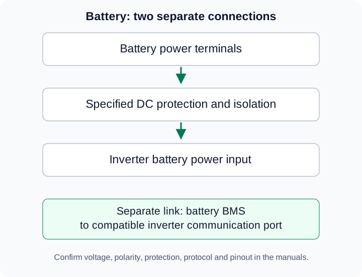
Most people searching for an inverter battery connection diagram want one picture that solves the whole job. That picture does not exist. The correct wiring depends on your bank voltage, your battery chemistry, your cable run length, and the current limits printed in your inverter manual. Change one of those and the conductor size, the protective device, and sometimes the topology change with it.
What does transfer is the topology. Every inverter battery connection has two paths. The DC power path carries full load current through protection and heavy conductors. The BMS data path is a low-voltage communication cable on its own protocol and pinout. Confusing the two causes most commissioning failures on lithium banks.
This guide covers the battery side of a hybrid system only. For the on-grid picture, with PV strings running to the inverter and the inverter to the meter, read the solar inverter wiring diagram guide.
Below: the series and parallel arithmetic, why 48 V banks replaced 12 V and 24 V, the connection order, protection placement, a cable sizing calculation with the formula shown, earthing, CAN bus wiring, and the mistakes that kill hardware.
Short version. An inverter battery connection diagram has one power path and one data path. The power path runs from the battery bank, through an overcurrent device close to the positive terminal, through a DC isolator, along sized conductors, to the inverter battery terminals. The data path is a separate BMS cable on the approved protocol and pinout. The two never share a cable.
How a battery-to-inverter circuit is laid out
The power path is a short, heavily protected DC circuit. It does not pass through the PV input or the backup output. Those are separate ports with separate functions.
| Order | Element | Function |
|---|---|---|
| 1 | Battery bank terminals | Source of power and of any fault current |
| 2 | Overcurrent device (fuse or DC breaker) | Protects the conductor downstream |
| 3 | DC isolator | Safe break for maintenance |
| 4 | Sized DC conductors | Carry current within drop and temperature limits |
| 5 | Inverter terminals (BAT+ / BAT-) | Entry to the charge and discharge stage |
| Alongside | BMS communication cable | Separate data link, own protocol and pinout |
| Alongside | Earthing and bonding conductor | Bonds racks and chassis to earth |
Read that as a functional order, not a claim that the BMS sits in series with the power. For the array-to-grid picture, see the full system wiring guide.
Series versus parallel: work the arithmetic first
Series adds voltage and keeps amp-hours constant. Parallel adds amp-hours and keeps voltage constant. Stored energy is identical either way, since energy is voltage multiplied by capacity. What changes is the current your cables carry.
Take four identical 12 V, 150 Ah units, arranged three ways, supplying 5,000 W of AC load at 90% efficiency.
| Configuration | Bank voltage | Capacity | Nominal energy | Current at 5 kW |
|---|---|---|---|---|
| 4 in series (4S) | 48 V | 150 Ah | 7.2 kWh | 116 A |
| 2 series, 2 parallel (2S2P) | 24 V | 300 Ah | 7.2 kWh | 231 A |
| 4 in parallel (4P) | 12 V | 600 Ah | 7.2 kWh | 463 A |
Energy is 7.2 kWh in all three rows. Current differs by a factor of four. That is the argument for choosing bank voltage deliberately.
Every unit in a series string carries the same current, so the weakest one sets the behaviour of the string. Match model, capacity, age, and firmware. Parallel strings need equal-length cables and a diagonal take-off, positive from one end of the bank and negative from the other.
One caution the arithmetic hides: packaged lithium products often forbid series connection outright. Pack voltage is fixed by the cell arrangement and the battery management system. Treat the table as illustration, not permission.
Why 48 V banks dominate, and when they do not
Resistive loss follows I²R. Double the voltage at the same power and current halves, so loss falls to a quarter. That is why 48 V became the default for residential and light commercial systems.
Assume 0.01 ohm of total cable and joint resistance, realistic for a short run.
| Bank voltage | Current at 5 kW | Loss through 0.01 ohm |
|---|---|---|
| 48 V | 116 A | 134 W |
| 24 V | 231 A | 534 W |
| 12 V | 463 A | 2,144 W |
The 12 V bank wastes 16 times the power of the 48 V bank as heat inside the cable, and needs lugs that are impractical to terminate neatly.
The tradeoff runs the other way at small scale. Below roughly 1 kW of continuous load, a 12 V or 24 V bank is cheaper and the current stays manageable.
Connect in this order, and check polarity at every step
Sequence matters because a partly connected DC circuit presents live terminals in unexpected places. Polarity matters because reversing it destroys the input stage on most designs.
- Isolate everything: the AC grid supply, the PV DC isolator, and the battery isolator.
- Confirm dead with a meter rated for the job. Prove the meter on a known source, before and after.
- Assemble the bank mechanically. Fit racks, cabinets, and busbars without energising anything.
- Make the series and parallel interconnections, with cable lengths equal within each parallel string.
- Fit earthing and bonding conductors to racks, enclosures, and the inverter chassis.
- Run the BMS cable and set address or DIP-switch configuration while the bank is isolated.
- Land the negative conductor at the inverter, then the positive, with the isolator still open.
- Verify polarity at the inverter terminals with a meter. Positive to BAT+, negative to BAT-.
- Torque every terminal to the manual figure, using a calibrated tool.
- Close the isolator, power the inverter, and confirm the data link before any charge or discharge.
Step 10 is the one people rush. Many systems must see valid BMS data before applying the correct charge limits.
Where the fuse, breaker and isolator belong
Protection and isolation are two jobs and usually two devices. The fuse or breaker protects the cable against fault current. The isolator lets a person open the circuit safely. One does not replace the other.
| Device | Position | Sizing note |
|---|---|---|
| Battery overcurrent device | Close to the battery positive terminal | Above continuous current, below derated cable ampacity |
| DC isolator | Between battery and inverter, reachable without tools | DC-rated, not a relabelled AC device |
| Inverter-side protection | At the inverter terminals, where specified | From the inverter manual only |
| String fusing in parallel banks | On each string, where the battery manual requires it | Per manufacturer instructions |
Worked example: sizing the battery cable
Worked example only. Arithmetic you can repeat with your own inputs, not a design for your installation, and no replacement for manufacturer instructions.
| Input | Value |
|---|---|
| Continuous AC load | 5,000 W |
| Nominal bank voltage | 48 V |
| Conversion efficiency | 90% |
| One-way cable run | 3 m |
| Allowed voltage drop | 1% of 48 V, so 0.48 V |
| Copper resistivity at 20 °C | 0.0172 ohm mm² per m |
Step 1, find the current.
I = P ÷ (V × efficiency) = 5,000 ÷ (48 × 0.90) = 115.7 A
Step 2, find conductor area from voltage drop.
A = (2 × L × I × resistivity) ÷ allowed drop = (2 × 3 × 115.7 × 0.0172) ÷ 0.48 = 24.9 mm²
Step 3, repeat at worst case. A bank does not sit at nominal. At 42 V the load draws 132.3 A, and the area becomes (2 × 3 × 132.3 × 0.0172) ÷ 0.48 = 28.4 mm².
Step 4, pick the standard size. 25 mm² passes the nominal case and fails the worst case, so 35 mm² is the practical selection.
Step 5, size the protective device. A common basis is 1.25 times continuous current: 115.7 × 1.25 = 144.6 A, so 150 A or 160 A is the nearest standard rating above. It must sit below the derated ampacity of the cable. The 1.25 factor is the continuous-load convention of the US National Electrical Code, explained for solar circuits by Mayfield Renewables. Indian practice follows IS 732 and the manufacturer’s instructions, so treat 1.25 as a starting point, not a rule that overrides the battery and inverter manuals.
This does not settle ampacity at your ambient temperature, derating for grouping and conduit, terminal ratings, or prospective fault current. Those come from IS 732:2019, the Code of Practice for Electrical Wiring Installations, Bureau of Indian Standards (2019).
Battery current limits of the Qbits QBH hybrids, and what they imply for cable
The worked example above started from a 5 kW load. A second way in is to start from the maximum charge and discharge current printed in the inverter datasheet. All QBH models print 48 V as the rated battery voltage and a maximum charging voltage of 60 V or less, configurable. The currents below are from the Qbits datasheets for the 3 to 6 kW, 7 to 8 kW and three-phase families, as printed in October 2026. The cable column reuses the method above at 3 m one way, 1% of 48 V drop and copper at 0.0172 ohm mm² per m.
| QBH model | Rated battery voltage | Max charge/discharge current | Conductor area for 1% drop over 3 m | Next standard size up | 1.25 × current |
|---|---|---|---|---|---|
| QBH-3KS48P | 48 V | 75 A | 16.1 mm² | 25 mm² | 93.8 A |
| QBH-3K6S48P | 48 V | 90 A | 19.4 mm² | 25 mm² | 112.5 A |
| QBH-4KS48P | 48 V | 100 A | 21.5 mm² | 25 mm² | 125.0 A |
| QBH-4K6S48P | 48 V | 110 A | 23.7 mm² | 25 mm² | 137.5 A |
| QBH-5KS48P, QBH-6KS48P | 48 V | 120 A | 25.8 mm² | 35 mm² | 150.0 A |
| QBH-7KS48P | 48 V | 175 A | 37.6 mm² | 50 mm² | 218.8 A |
| QBH-7K6S48P, QBH-8KS48P | 48 V | 190 A | 40.9 mm² | 50 mm² | 237.5 A |
| QBH-5KS48P3 | 48 V | 120 A | 25.8 mm² | 35 mm² | 150.0 A |
| QBH-6KS48P3 | 48 V | 125 A | 26.9 mm² | 35 mm² | 156.3 A |
| QBH-7KS48P3 | 48 V | 150 A | 32.2 mm² | 35 mm² | 187.5 A |
| QBH-8KS48P3 | 48 V | 190 A | 40.9 mm² | 50 mm² | 237.5 A |
| QBH-10KS48P3 | 48 V | 210 A | 45.2 mm² | 50 mm² | 262.5 A |
| QBH-12KS48P3 | 48 V | 250 A | 53.8 mm² | 70 mm² | 312.5 A |
Read the table as an upper bound, not a design. It assumes the inverter runs at its full battery current, which most homes never do. The real limit is the lower of the inverter figure and the battery’s own maximum, so a battery rated below the inverter figure sets the current you size for. Ampacity at your ambient temperature, grouping, terminal ratings and prospective fault current still come from IS 732:2019 and the manuals. The “next standard size” column rounds to the usual metric series of 25, 35, 50 and 70 mm².
Earthing and bonding the battery circuit
Earthing protects people from fault current on metalwork. Bonding ties that metalwork together so it sits at the same potential. Neither job involves connecting a live battery conductor to earth.
Bond the battery rack, the enclosure, and the inverter chassis to the installation earthing system, per IS 3043:2018, the Code of Practice for Earthing, Bureau of Indian Standards (2018). Use a single identified point of connection.
Most 48 V lithium banks are specified to float, meaning neither pole is referenced to earth. That is deliberate. Insulation monitoring and earth-fault detection rely on it, and earthing a pole quietly disables them.
Never use a battery negative conductor as an earthing conductor. At handover, ask for recorded earth continuity and insulation resistance results.
BMS communication wiring for lithium banks
On a lithium bank the communication cable is a protective element, not a convenience feature. The CAN bus or RS485 link carries state of charge, cell voltages, pack temperature, and permitted charge and discharge limits into the inverter. Without it, the inverter charges blind to a fixed voltage setpoint.
That matters most for LiFePO4 chemistry, where the voltage curve is flat through the middle of the range, so voltage alone is a poor proxy for state of charge. The link also lets the pack request a derate as cell temperature rises, and allows depth of discharge limits to be respected rather than estimated.
Four details cause most communication failures.
- Pinout, not connector. The socket may look like an RJ45 Ethernet port, but the pin assignment is proprietary. A standard patch cable is usually wrong, and on some pinouts it puts supply voltage on a data pin.
- Termination. CAN networks normally need a 120 ohm resistor at each end of the bus. A setting copied from another brand rarely works.
- Addressing. One unit is master and the rest slaves, usually set by DIP switches. Duplicate addresses give a bus that looks connected and carries nothing.
- Routing. Keep the cable away from DC power conductors and use shielded cable where specified. Switching noise corrupts frames.
More on what the BMS reports sits in the BMS explainer. If communication fails, capture the exact alarm text, then ask the supplier for the approved recovery procedure.
Lead-acid versus lithium: what changes in the wiring
The power path looks similar on paper. The obligations around it differ, and installers who carry lead-acid habits onto a lithium bank get caught out.
| Aspect | Lead-acid bank | Lithium (LiFePO4) bank |
|---|---|---|
| Communication cable | Usually none; charging follows a voltage profile | Normally required, CAN or RS485 |
| Usable depth of discharge | Commonly around 50% | Typically 80% to 90%, per the specification |
| Series and parallel freedom | 12 V units often combined into 48 V strings | Packaged units frequently forbid series |
| Ventilation | Flooded types vent hydrogen, so housing must be ventilated | Sealed; the need is thermal, not gas |
| Temperature handling | Charge voltage compensated by external sensor | Pack reports temperature and requests derating |
| Fault current | High | Higher and longer, so breaking capacity matters more |
Usable energy follows from that second row. Take the 7.2 kWh bank from earlier. At a 50% limit it gives roughly 3.6 kWh usable. At 85% it gives roughly 6.1 kWh. Those percentages are assumptions, so substitute your own specification. For a full method, use the battery sizing walkthrough.
Nine wiring mistakes that destroy equipment
Each of these has a specific failure mode. None is theoretical.
| Mistake | What it causes |
|---|---|
| Reversed polarity at the inverter | DC input stage failure, often not field-repairable |
| No overcurrent device in the run | Full fault current into a short, melting cable and terminals |
| Undersized conductors | Voltage drop, premature low-voltage cut-outs, hot insulation |
| Loose or untorqued terminals | High-resistance joints that heat up and burn off the lug |
| Unequal cable lengths in parallel | Uneven current sharing, so one string ages faster |
| BMS cable in an Ethernet or monitoring port | No data link, so the inverter charges blind on voltage |
| Patch cable on a proprietary CAN pinout | Comms failure, and on some pinouts supply voltage on a data pin |
| Mixing chemistries, ages, or capacities | The weakest unit governs the bank and gets over-discharged |
| Earthing a pole on a bank specified to float | Earth-fault detection stops working silently |
The silent ones are the dangerous ones. A loose terminal and a defeated earth-fault detector both pass a handover test. Insist on recorded torque and insulation results.
Safety: DC battery work belongs with a qualified electrician
A 48 V DC bank is not a shock hazard the way a 230 V AC circuit is. It is a severe arc and burn hazard, a risk people underestimate.
A lithium bank compounds it. Internal resistance is low, so short-circuit current is very high and sustained. A spanner dropped across two terminals becomes the fault path. Remove rings and watches, and use insulated tools.
Electrical installation work in India falls under the Central Electricity Authority (Measures relating to Safety and Electric Supply) Regulations, 2023, and licensing sits with the state electrical inspectorate. Rules vary by state and by DISCOM. Engage a licensed electrician who works to the manufacturer instructions and hands over test records.
One note on the AC side. The Qbits single-phase hybrid datasheet prints “Switching as uninterruptible power supply within 10 seconds”. Take that phrasing as written and check it against your backup loads.
The Bottom Line
An inverter battery connection diagram becomes useful once four things are fixed: bank voltage, protection placement, conductor size, and whether a BMS data link is required. The arithmetic here transfers anywhere. The model-specific limits do not.
- Write down your numbers first. Continuous load, bank voltage, run length, and allowed voltage drop. Without those four inputs, no cable or fuse selection is defensible.
- Get both manuals before buying anything. The inverter and battery manuals decide series and parallel limits, protocol, pinout, and protection type. An interface label is not a compatibility statement.
- Check your DC design, then talk to us. Run the array through the string sizing calculator, then contact Qbits with your inverter model and battery documentation to request the matching compatibility information.
Qbits inverters for this guide
Specs below come from each model's datasheet. Confirm the exact model and current written terms with Qbits before you buy.
QBH 3KS/3K6S/4KS/4K6S/5KS/6KS48P
- Power
- 3–6 kW
- Phase
- Single-phase
- MPPT
- 1 or 2 MPPTs by model
QBH 7KS/7K6S/8KS48P
- Power
- 7–8 kW
- Phase
- Single-phase
- MPPT
- Dual-MPPT
QBH 5/6/7/8/10/12KS48P3
- Power
- 5–12 kW
- Phase
- Three-phase
- MPPT
- 1 or 2 MPPTs by model
Frequently Asked Questions
Are battery power and BMS communication the same connection?
Should I wire my batteries in series or parallel?
Why do hybrid systems use 48 V instead of 12 V or 24 V?
Where should the fuse go between the battery and the inverter?
What size cable do I need between a 48 V battery and a 5 kW hybrid inverter?
Can I connect a lithium battery to an inverter without a CAN or RS485 cable?
Do I need to earth the battery bank?
Can I mix old and new batteries in the same bank?
Is inverter battery wiring a DIY job?

Keyur Rakholiya CTO, Qbits Energy
Listed by Qbits as its CTO. Current role, technical responsibilities and credentials require confirmation by the company owner.