
Solar Inverter Grounding: 14 Critical Safety FAQs for EPCs

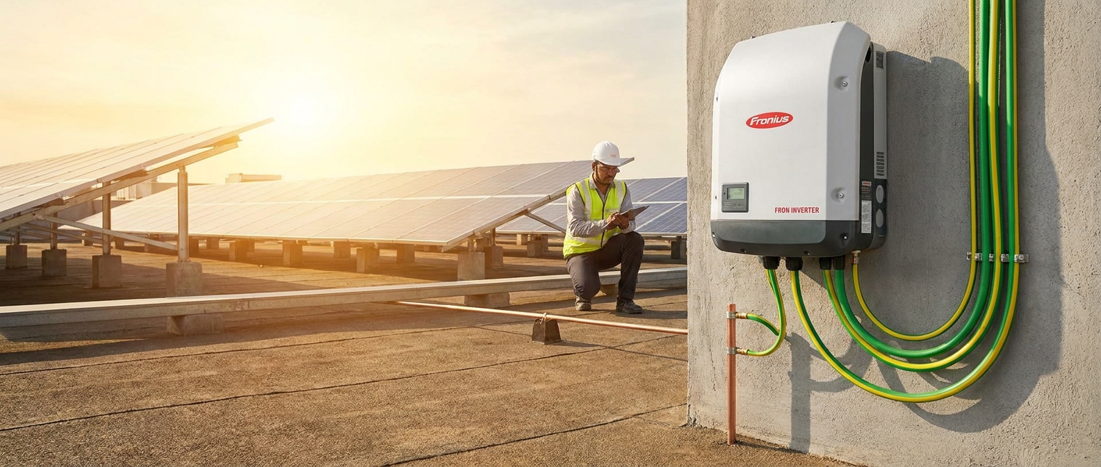
Inverter grounding is one of the most critical yet frequently misunderstood aspects of solar PV installation in India. For EPCs and installers, a grounding error is not just a technical oversight — it can mean equipment failure, voided warranties, regulatory non-compliance, and serious safety hazards for personnel. With India’s solar capacity expanding rapidly in 2026, getting grounding right from day one is essential for every professional installation.
This comprehensive FAQ guide answers the 14 most pressing questions about solar inverter grounding and earthing that Indian EPCs encounter on the job. Whether you are commissioning a 5 kW rooftop system or a 500 kW commercial plant, these answers will help you install with confidence, protect your clients’ investments, and stay compliant with Indian electrical standards.
Why Inverter Grounding Is Non-Negotiable for Solar Installations in India
India’s electrical environment presents unique challenges for solar installations. Frequent voltage fluctuations, monsoon-season lightning strikes, high ambient temperatures, and variable grid quality all put stress on solar inverters. Proper inverter grounding is the first line of defense against all of these threats.
Grounding protects both equipment and people. It provides a safe path for fault currents, prevents dangerous voltage buildup on metal surfaces, and ensures that surge protection devices (SPDs) can do their job effectively. Without a solid grounding system, even the highest-quality inverter is vulnerable to premature failure.
Indian regulations are also clear on this point. The Central Electricity Authority (CEA) Technical Standards for Connectivity and IS 3043 (Code of Practice for Earthing) both mandate proper earthing for all grid-connected solar PV systems. Non-compliance can result in failed inspections, rejected DISCOM approvals, and liability exposure for EPCs.
The 14 FAQs below address every major grounding concern — from basic definitions to advanced compliance checks — so your team has a reliable reference for every installation.
FAQ 1, 3: Inverter Grounding Fundamentals Every EPC Must Understand
FAQ 1: What is the difference between grounding and earthing in a solar inverter system?
In Indian electrical practice, the terms grounding and earthing are often used interchangeably, but they refer to slightly different concepts. Earthing (the term preferred in IS 3043 and Indian standards) refers to connecting the non-current-carrying metal parts of the system, such as the inverter chassis, module frames, and mounting structures, to the earth. This protects against electric shock if a fault causes those parts to become live.
Grounding in the broader sense also includes the intentional connection of a current-carrying conductor (such as the neutral in an AC system) to earth for system stability. In solar PV, this distinction matters because the DC side and AC side have different grounding requirements. Most modern transformerless inverters used in India operate with an ungrounded (floating) DC input, while the AC output neutral is grounded at the main distribution board.
For EPCs, the practical takeaway is this: every metal surface that a person could touch must be earthed, and the AC neutral must be grounded at the point of common coupling (PCC) with the grid.
FAQ 2: Which components of a solar PV system require grounding?
A complete solar PV system has multiple components that require proper inverter grounding and earthing. Here is a full list:
- Solar inverter chassis: The metal body of the inverter must be connected to the earthing system, regardless of whether it is a wall-mounted or floor-standing unit.
- Solar module frames: All aluminum module frames must be bonded together and connected to the earthing conductor. This prevents dangerous voltage buildup if a module develops an insulation fault.
- Mounting structures: Rooftop mounting rails, clamps, and support structures must all be bonded to earth.
- DC combiner boxes and string boxes: Metal enclosures housing DC fuses, SPDs, and disconnects must be earthed.
- AC distribution boards and MCBs: All metal enclosures on the AC side require earthing.
- Surge Protection Devices (SPDs): Both DC-side and AC-side SPDs must be connected to the earthing system to function correctly.
- Cable trays and conduits: Metal cable management systems must be bonded to the earthing conductor.
Missing any of these components in your earthing design is a common cause of system failures and failed inspections. A thorough inverter selection and installation checklist should always include a complete earthing component audit.
FAQ 3: What are the Indian electrical code requirements for inverter grounding?
Indian EPCs must comply with several overlapping standards for solar inverter grounding:
- IS 3043:2018, Code of Practice for Earthing: The primary Indian standard governing earthing design, electrode types, conductor sizing, and testing.
- CEA (Technical Standards for Connectivity of the Distributed Generation Resources) Regulations, 2013 (amended 2019): Mandates earthing for all grid-connected solar systems and specifies requirements for protection systems.
- IS 13947 / IEC 60947: Governs low-voltage switchgear and controlgear, relevant for AC-side protection and earthing.
- IEC 62305: Lightning protection standard, which directly impacts earthing design in lightning-prone regions of India.
- BIS Certification requirements: Inverters sold in India must meet BIS standards, which include earthing terminal requirements.
State-level DISCOMs may also have additional earthing requirements for grid-connected systems. Always verify local DISCOM guidelines before finalizing your earthing design.
FAQ 4, 6: Proper Grounding Techniques and Installation Standards
FAQ 4: What is the correct grounding conductor size for solar inverters in India?
Conductor sizing for inverter grounding is governed by IS 3043 and depends on the size of the phase conductor in the circuit. As a general rule:
- For phase conductors up to 16 mm², the earthing conductor must be the same cross-sectional area.
- For phase conductors between 16 mm² and 35 mm², the earthing conductor must be at least 16 mm².
- For phase conductors above 35 mm², the earthing conductor must be at least half the cross-sectional area of the phase conductor.
For most residential rooftop systems (3, 10 kW), a minimum 6 mm² copper earthing conductor is standard. For commercial and industrial systems above 50 kW, earthing conductors of 25 mm² or larger are typically required. Always use copper conductors for earthing in solar installations, aluminum is not recommended due to its susceptibility to corrosion at connection points, especially in coastal and humid Indian climates.
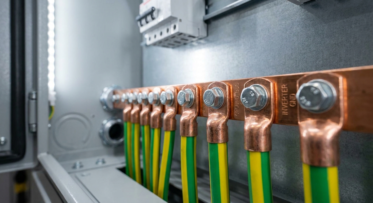
The earthing conductor must be protected from mechanical damage where it runs along walls or through conduits, and all connections must use proper compression lugs or exothermic welding, never simple twisted connections.
FAQ 5: How should the grounding electrode system be designed for rooftop solar?
The grounding electrode system is the physical connection between your earthing conductor and the earth itself. For rooftop solar installations in India, the most common electrode types are:
- Plate electrodes: Copper or GI plates buried at a minimum depth of 3 meters. Suitable for most soil conditions.
- Pipe electrodes: GI or copper pipes driven vertically into the ground. Minimum 2.5 meters depth as per IS 3043.
- Rod electrodes: Copper-bonded steel rods, typically 16 mm diameter and 3 meters long. Increasingly popular for urban rooftop installations due to ease of installation.
The target earth resistance for solar PV systems should be below 5 ohms as per IS 3043, and ideally below 1 ohm for systems with sensitive electronics. In high-resistivity soils (common in rocky or sandy regions of Rajasthan, Gujarat, and parts of Maharashtra), chemical earthing compounds or multiple electrodes in parallel may be needed to achieve the required resistance.
For multi-story buildings where driving electrodes to ground level is impractical, consult a qualified electrical engineer for alternative earthing solutions such as foundation earthing or ring earthing systems.
FAQ 6: What is the difference between AC and DC grounding in a solar inverter system?
This is one of the most important distinctions in solar inverter grounding design. The AC and DC sides of a solar system have fundamentally different grounding requirements.
AC-side grounding follows standard electrical installation practice. The neutral conductor is grounded at the main distribution board, and all metal enclosures are earthed. This is straightforward and follows IS 3043 and standard wiring regulations.
DC-side grounding is more complex. Most modern transformerless solar inverters, including the majority of on-grid and hybrid inverters used in India today, have an ungrounded (floating) DC input. This means neither the positive nor negative DC conductor is intentionally connected to earth. Instead, the inverter continuously monitors the insulation resistance between the DC conductors and earth (this is the “ISO monitoring” or “insulation monitoring” function you see in inverter specifications).
If the insulation resistance drops below a safe threshold (typically 1 MΩ for residential systems), the inverter will trigger an ISO fault and disconnect from the grid. This is a safety feature, not a malfunction. However, all DC-side metal components (module frames, mounting structures, string box enclosures) must still be earthed even though the DC conductors themselves are not.
Some older transformer-based inverters and certain utility-scale systems use a grounded DC negative. If you are working with such systems, follow the manufacturer’s specific grounding instructions carefully, as connecting an ungrounded inverter to a grounded DC system can cause serious damage.
FAQ 7, 9: Surge Protection and Inverter Grounding Integration
FAQ 7: How does surge protection integrate with inverter grounding?
Surge Protection Devices (SPDs) and the earthing system work together as an integrated protection system. An SPD cannot function without a proper earth connection, it works by diverting surge energy to earth, so if the earth path has high resistance or poor connections, the SPD cannot protect the inverter effectively.
For solar PV systems in India, SPDs are required on both the DC side (between the string combiner and the inverter) and the AC side (at the main distribution board). The SPD earth terminal must be connected to the same earthing system as the inverter chassis, using the shortest possible conductor path to minimize impedance.
Qbits solar inverters include built-in DC and AC Surge Protection Devices as standard, which simplifies installation and ensures the SPD is properly integrated with the inverter’s internal protection circuits. This is particularly valuable in India’s lightning-prone regions, where external surge events are a leading cause of inverter failure.
For more information on how monitoring systems can help detect grounding and surge-related issues in real time, see our guide on Solar Inverter Monitoring Systems in India (2026).
FAQ 8: What SPD ratings are required for solar inverters in India’s lightning-prone regions?
India has significant lightning activity, particularly in the northeastern states, West Bengal, Odisha, and parts of central India. Even in lower-risk regions, monsoon-season lightning is a real threat to solar installations. The correct SPD ratings depend on the system voltage and the lightning risk level of the installation site.
For DC-side SPDs on residential and small commercial systems (up to 1000V DC):
- Type 2 SPD (Class II) is the minimum requirement for most installations.
- Type 1+2 combined SPD is recommended for installations in high lightning-risk zones or where an external lightning protection system is present.
- Minimum voltage protection level (Up): ≤ 2.5 kV for 1000V DC systems.
- Nominal discharge current (In): Minimum 5 kA, recommended 20 kA for high-risk areas.
For AC-side SPDs:
- Type 2 SPD rated for the system’s AC voltage (typically 230V single-phase or 415V three-phase).
- Voltage protection level (Up): ≤ 1.5 kV.
- Nominal discharge current (In): Minimum 5 kA.
Always verify SPD requirements with the local DISCOM and follow IEC 61643-11 (DC SPDs) and IEC 61643-11 (AC SPDs) for product selection.
FAQ 9: Can poor grounding void an inverter warranty?
Yes, and this is a critical point that every EPC must communicate clearly to clients. Improper inverter grounding is one of the most common reasons inverter warranty claims are rejected by manufacturers.
Most inverter warranty terms explicitly require that the inverter be installed in accordance with the manufacturer’s installation manual and applicable electrical standards. If an inverter fails due to a surge event, insulation fault, or corrosion caused by improper earthing, the manufacturer can, and typically will, reject the warranty claim on the grounds of improper installation.
Qbits’ 12-year full replacement warranty is designed to give EPCs and end customers genuine long-term protection. To keep that warranty valid, installations must follow the grounding specifications in the Qbits installation manual and comply with IS 3043 and CEA regulations. Qbits’ digital warranty system makes it easy to register and document installations, creating a clear record of compliance that protects both the EPC and the end customer.
For a broader perspective on how installation quality affects long-term inverter value, read our Solar Inverter Lifespan: Complete Financial Planning Guide.
FAQ 10, 11: Common Inverter Grounding Mistakes That Cause System Failures
FAQ 10: What are the most common inverter grounding mistakes EPCs make?
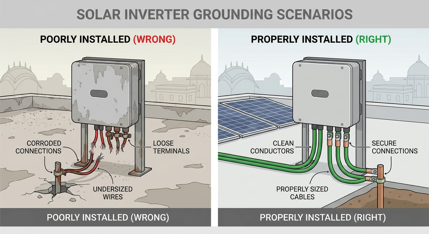
After reviewing hundreds of solar installations across India, these are the grounding errors that appear most frequently, and cause the most damage:
- Undersized earthing conductors: Using 2.5 mm² wire where 6 mm² or larger is required. This increases earth path resistance and reduces the effectiveness of surge protection.
- Shared neutral and earth conductors: Combining the neutral and earth at points other than the main earthing terminal (MET) creates dangerous potential differences and can cause nuisance tripping of RCDs.
- Poor electrode installation: Driving earth rods into dry, rocky, or high-resistivity soil without testing resistance. An earth resistance above 5 ohms provides inadequate protection.
- Loose or corroded connections: Using improper connectors, failing to apply anti-oxidant compound on aluminum connections, or not torquing terminals to the manufacturer’s specification. Loose connections increase resistance over time and can cause arcing.
- Omitting module frame earthing: Earthing only the inverter chassis while leaving module frames unearthed. This is a serious shock hazard and a common cause of insulation fault alarms.
- Incorrect SPD earth connection: Running the SPD earth wire in a long loop rather than the shortest possible path to the earthing busbar. Every extra meter of conductor adds impedance and reduces SPD effectiveness.
- Not testing earth resistance after installation: Assuming the earthing system is adequate without measuring actual resistance with an earth resistance tester.
- Using galvanized iron (GI) conductors in corrosive environments: In coastal areas or industrial zones, GI conductors corrode rapidly. Copper or tinned copper is required.
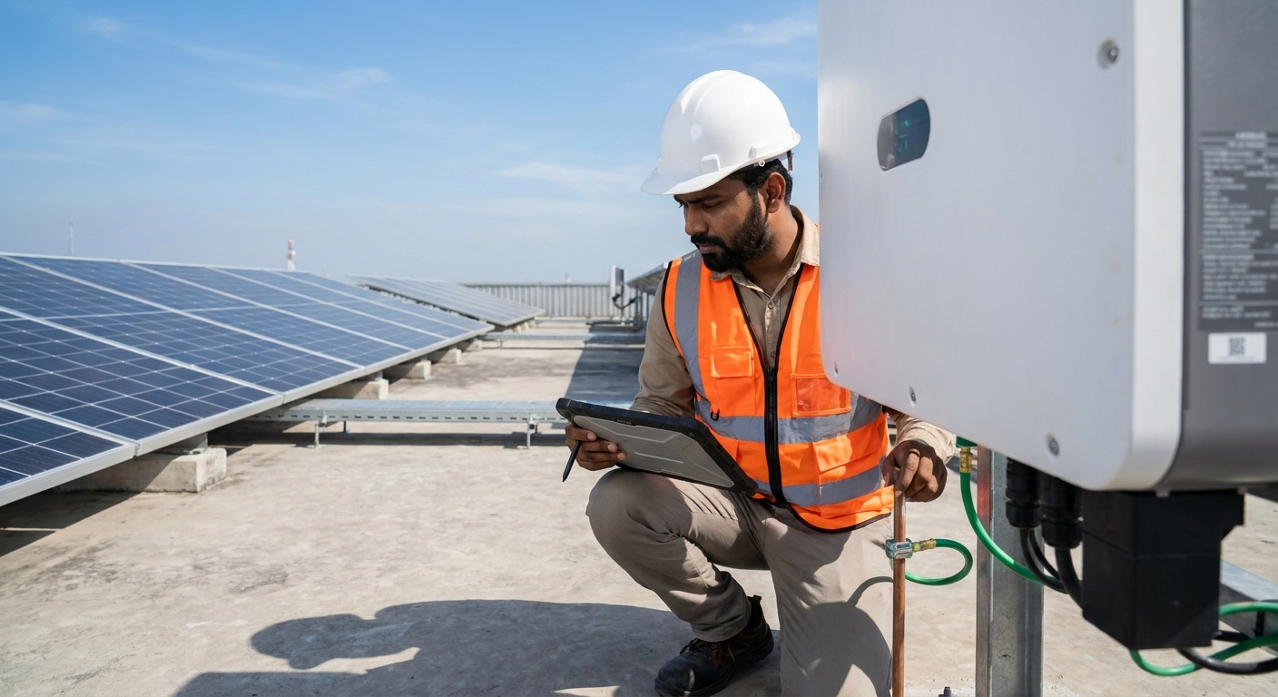
FAQ 11: How do you test and verify that inverter grounding is correct after installation?
Testing is not optional, it is a mandatory step in any professional solar installation. Here is the standard verification process for inverter grounding:
- Earth resistance test: Use a calibrated earth resistance tester (3-point fall-of-potential method as per IS 3043) to measure the resistance of each earth electrode. Target: below 5 ohms, ideally below 1 ohm.
- Continuity test: Use a low-resistance ohmmeter to verify continuity between all earthed metal parts (module frames, mounting structures, inverter chassis, enclosures) and the main earthing terminal. Resistance should be below 0.1 ohms for each connection.
- Insulation resistance test: Use a 500V or 1000V insulation resistance tester (megger) to verify that DC cable insulation is intact. Minimum acceptable value: 1 MΩ per IEC 62446.
- Inverter ISO monitoring check: After commissioning, verify that the inverter’s insulation monitoring function is active and not showing any ISO fault. A healthy reading confirms that the DC side is properly isolated from earth.
- Visual inspection: Check all connections for proper torque, correct conductor sizing, absence of corrosion, and proper cable routing and protection.
All test results should be documented in the commissioning report and retained for warranty and regulatory compliance purposes. Qbits’ technical support team can assist EPCs with commissioning documentation requirements.
FAQ 12, 13: Grounding for Hybrid and On-Grid Inverters in Indian Conditions
FAQ 12: Are grounding requirements different for hybrid inverters vs on-grid inverters?
The fundamental inverter grounding principles are the same for both hybrid and on-grid inverters, but hybrid systems have additional complexity due to the battery connection.
For on-grid inverters, the grounding system covers the DC input (PV strings), the inverter chassis, and the AC output connection to the grid. The system is relatively straightforward.
For hybrid inverters, you must also consider:
- Battery bank earthing: The battery enclosure and any metal battery rack must be earthed. The battery DC conductors themselves are typically ungrounded (floating), similar to the PV DC input.
- Additional SPD requirements: The battery connection introduces another potential surge entry point. Some hybrid inverter manufacturers recommend additional SPDs on the battery DC input.
- EPS (Emergency Power Supply) output earthing: Hybrid inverters with an EPS or backup output create an isolated AC microgrid during grid outages. The neutral of this EPS output must be earthed locally (at the inverter or at the backup load panel) to provide shock protection during islanded operation.
- Increased earth fault sensitivity: Hybrid systems with larger battery banks have higher capacitance to earth, which can trigger ISO fault alarms if earthing is not properly designed.
Qbits hybrid inverters are designed with these complexities in mind, and the installation manual provides specific grounding diagrams for both grid-connected and backup operation modes. To understand the full range of Qbits hybrid and on-grid solutions, visit the Qbits product range.
FAQ 13: How does inverter grounding protect against India’s frequent voltage fluctuations?
India’s grid is characterized by voltage fluctuations, frequency variations, and occasional power surges, particularly in rural areas and during peak demand periods. Proper inverter grounding plays a direct role in protecting against these conditions.
When a voltage surge enters the system through the grid connection, the AC-side SPD diverts the surge energy to earth. Without a low-resistance earth path, this surge energy has nowhere to go and passes through the inverter’s internal components, causing damage. A well-designed earthing system with resistance below 1 ohm ensures that surge energy is dissipated safely and quickly.
Grounding also stabilizes the common-mode voltage on the DC side. In transformerless inverters, the DC bus floats relative to earth. If the earth connection is poor or missing, common-mode noise from the grid can couple into the DC side, causing nuisance ISO faults and potentially stressing the inverter’s capacitors and switching components over time.
Additionally, proper earthing of module frames prevents the buildup of leakage currents that can cause Potential Induced Degradation (PID) in solar modules, a significant long-term energy yield loss issue in Indian conditions where high temperatures and humidity accelerate PID effects.
For EPCs evaluating inverters for India’s challenging grid conditions, our guide on Solar Inverter Manufacturers in India: Complete Evaluation Guide for EPCs & Distributors (2026) covers how to assess inverter robustness for local conditions.
FAQ 14: How Does Inverter Grounding Affect Long-Term System Reliability and ROI?
The connection between inverter grounding quality and long-term system ROI is direct and significant. Here is how proper grounding translates into financial outcomes:
Reduced Equipment Failure Rates
Inverters that are properly grounded experience significantly fewer surge-related failures. In India’s lightning-active regions, a single surge event can destroy an unprotected inverter. Replacing an inverter mid-project not only costs money but also causes generation losses and damages the EPC’s reputation. Proper grounding, combined with quality SPDs, is the most cost-effective insurance against surge damage.
Warranty Protection
As discussed in FAQ 9, proper grounding is a prerequisite for valid warranty claims. A 12-year warranty is only valuable if it can actually be claimed. EPCs who document their grounding installations thoroughly, with test results and commissioning reports, protect both their clients and their own business from warranty disputes.
Lower Maintenance Costs
Systems with poor grounding tend to generate more fault alarms, require more service visits, and experience higher component degradation rates. Proper grounding reduces nuisance faults, extends component life, and lowers the total cost of ownership over the system’s 25-year lifespan.
PID Prevention and Energy Yield
As noted in FAQ 13, proper module frame earthing prevents PID, which can reduce module output by 10, 30% over time. For a 100 kW commercial system, preventing PID through correct grounding can protect hundreds of thousands of rupees in energy yield over the system’s lifetime.
Qbits’ Built-In Grounding Support
Qbits inverters are engineered to support proper grounding from the ground up. Every unit includes:
- Dedicated earthing terminals with clear labeling and torque specifications
- Built-in DC and AC SPDs that integrate seamlessly with the earthing system
- Continuous insulation monitoring that alerts installers and operators to any degradation in DC-side insulation
- IP66 weather protection that prevents moisture ingress, a leading cause of insulation degradation and grounding faults in Indian rooftop conditions
- AI-powered WhatsApp monitoring that sends real-time alerts for ISO faults, earth leakage events, and other grounding-related issues
These features work together to make proper inverter grounding easier to achieve and easier to maintain over the inverter’s full service life. Learn more about how smart monitoring supports grounding health in our article on Solar Inverter Monitoring Systems in India (2026).
Inverter Grounding Compliance Checklist for Indian EPCs
Use this quick-reference checklist to ensure every installation meets Indian standards for inverter grounding and earthing compliance.
Pre-Installation
- Confirm soil resistivity at the installation site and select appropriate electrode type
- Design earthing system to achieve below 5 ohms resistance (target below 1 ohm)
- Select copper earthing conductors sized per IS 3043 for the system’s phase conductor size
- Specify Type 2 SPDs (or Type 1+2 for high lightning-risk zones) for both DC and AC sides
- Review inverter manufacturer’s grounding requirements and installation manual
- Verify local DISCOM earthing requirements for grid-connected systems
During Installation
- Install earth electrodes to the required depth and in suitable soil conditions
- Bond all module frames, mounting structures, and metal enclosures to the earthing conductor
- Connect inverter chassis to the earthing system using the dedicated earth terminal
- Install SPDs with the shortest possible earth conductor path to the earthing busbar
- Use compression lugs or exothermic welding for all earthing connections, no twisted joints
- Apply anti-oxidant compound on all connections in humid or coastal environments
- Protect earthing conductors from mechanical damage with conduit or cable tray
Post-Installation Testing
- Measure earth electrode resistance with a calibrated earth resistance tester (target: below 5 ohms)
- Test continuity between all earthed components and the main earthing terminal (target: below 0.1 ohms)
- Perform insulation resistance test on all DC cables (minimum: 1 MΩ)
- Verify inverter ISO monitoring is active and showing no faults after commissioning
- Document all test results in the commissioning report
- Register the installation in the inverter manufacturer’s warranty system
Documentation for Compliance
- Retain earth resistance test certificates for DISCOM submission
- Include earthing design drawings in the as-built documentation package
- Record all conductor sizes, electrode types, and connection methods used
- Register warranty with the manufacturer’s digital system immediately after commissioning
For guidance on how grounding quality fits into the broader inverter selection process, see our detailed resource: Solar Inverter Selection: 10 Critical Criteria for EPCs.
Key Takeaway: Proper inverter grounding is not a box-ticking exercise, it is the foundation of a safe, reliable, and financially sound solar installation. Every rupee invested in a correct earthing system pays back many times over in avoided failures, valid warranty claims, and long-term energy yield protection.
Partner with Qbits for Grounding-Ready Solar Inverters
Getting inverter grounding right starts with choosing an inverter that is engineered to support it. Qbits solar inverters are built with dedicated earthing terminals, integrated SPDs, continuous insulation monitoring, and IP66 weather protection, giving Indian EPCs a solid technical foundation for every installation. Backed by a 12-year full replacement warranty and a digital warranty registration system, Qbits makes it straightforward to protect your installations and your clients’ investments for the long term.
If you are an EPC, installer, or distributor looking for a reliable inverter partner for your next project, we would be glad to help. Reach out to the Qbits team on WhatsApp to discuss your project requirements and get technical guidance on grounding-compliant inverter solutions. You can also become a Qbits channel partner and bring India’s next-generation solar inverter technology to your customers. For any technical queries or after-sales support, visit our support portal, our team is ready to assist.
Follow Qbits on LinkedIn and Instagram for the latest technical updates, installation best practices, and product news from India’s solar industry.
This blog post was written using thestacc.com