
Inverter Clipping Explained: 12 FAQs About DC Oversizing

For solar EPCs and installation companies across India, few technical concepts generate as much confusion—and unnecessary concern—as inverter clipping. When designing solar systems with modern high-wattage panels, understanding the relationship between DC oversizing and clipping becomes essential for optimizing both system performance and project economics. This comprehensive FAQ guide addresses the twelve most critical questions about inverter clipping, helping you make informed design decisions and confidently explain this technical concept to your clients.
Whether you’re specifying inverters for a commercial rooftop installation in Mumbai or a residential project in Rajasthan, mastering inverter clipping principles will improve your system designs, enhance ROI for clients, and prevent costly over-specification of equipment. Let’s demystify this important aspect of solar system engineering.
What Is Inverter Clipping in Solar Power Systems?
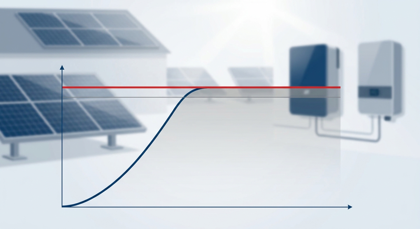
Inverter clipping occurs when the DC power generated by your solar array exceeds the maximum AC output capacity of the inverter. During these peak production moments—typically around solar noon on clear days—the inverter reaches its rated capacity limit and cannot convert all available DC power to AC electricity. The excess power is “clipped” or curtailed, appearing as a flat-topped power curve rather than the typical bell-shaped production profile.
Think of it this way: if you have a 50 kW inverter connected to a 60 kW solar array, during optimal conditions when your panels generate their full 60 kW, the inverter can only output its maximum 50 kW. The remaining 10 kW of potential production is clipped. This isn’t a malfunction, it’s a predictable outcome of intentional system design that balances equipment costs against energy production.
In practical terms for Indian installations, clipping typically occurs for only a few hours per year during peak irradiance conditions. The rest of the time, your solar array operates below its nameplate capacity due to factors like temperature derating, soiling, panel degradation, and suboptimal sun angles. This is precisely why strategic DC oversizing makes economic sense.
Modern solar inverter selection must account for clipping as part of the overall system optimization process. When you understand that clipping affects only a small percentage of annual energy production while allowing you to capture significantly more energy during morning, evening, and cloudy conditions, the design logic becomes clear.
Why Does Inverter Clipping Occur?
The fundamental cause of inverter clipping is straightforward: the DC array capacity exceeds the inverter’s AC output rating. However, several technical and environmental factors determine when and how frequently clipping events occur in real-world installations.
From a technical perspective, every inverter has a maximum continuous AC power rating, the upper limit of electricity it can safely convert and output to the grid or load. This rating is determined by the inverter’s internal components, including power electronics, transformers (if applicable), cooling systems, and thermal management capabilities. When DC input power pushes against this ceiling, the inverter’s maximum power point tracking (MPPT) algorithm adjusts to limit power conversion, resulting in clipping.
Environmental conditions play a crucial role in triggering clipping events. Peak irradiance levels above 1000 W/m²—common in India’s high-solar-resource regions, can push well-designed arrays beyond their standard test condition (STC) ratings. Cool, clear mornings in winter months often produce the highest clipping potential, as panels operate more efficiently at lower temperatures while receiving strong irradiance.
The proliferation of high-wattage solar panels in 2026 has increased clipping likelihood across the industry. Modern panels rated at 650W, 700W, and even 750W pack more power into the same physical footprint, meaning that arrays designed to fit available roof space often exceed traditional DC-to-AC ratios. Qbits inverters support up to 100% DC oversizing, providing the flexibility needed to accommodate these powerful modern panels while maintaining system reliability.
Panel orientation and tilt also influence clipping patterns. Arrays optimized for peak production (south-facing at optimal tilt angles in India) experience more frequent clipping than those with east-west orientations or suboptimal tilts. Multi-MPPT inverter configurations can help manage clipping by allowing different array orientations to peak at different times throughout the day.
Is Inverter Clipping Harmful to Solar Systems?
This is perhaps the most important question for EPCs to understand: inverter clipping within manufacturer specifications is not harmful to your solar system. Despite common misconceptions, clipping does not damage inverters, void warranties, or compromise system longevity when properly designed.
Modern solar inverters are engineered with robust protection mechanisms specifically designed to handle clipping events. When the inverter reaches its maximum output capacity, sophisticated control algorithms smoothly limit power conversion without creating electrical stress on components. The inverter doesn’t “fight” against excess DC power, it simply operates at its rated maximum while the MPPT system adjusts the operating point on the panel’s I-V curve.
Thermal management systems in quality inverters handle clipping scenarios effectively. During clipping events, the inverter operates at its designed maximum load, which is well within the thermal envelope established during engineering and testing. Premium inverters like those from Qbits undergo 1000+ automated quality tests that include extended operation at maximum capacity, ensuring components can handle sustained peak output without degradation.
From a warranty perspective, clipping within the manufacturer’s specified DC oversizing limits is fully covered. The key is adhering to published specifications, for example, if an inverter supports 100% DC oversizing (a DC-to-AC ratio of 2.0:1), designing within this parameter ensures full warranty protection. Exceeding manufacturer limits, however, can void warranty coverage and potentially create safety issues.
It’s worth noting that clipping actually reduces stress on inverters compared to rapid power fluctuations from passing clouds or intermittent shading. The steady-state operation at maximum capacity during clipping is a benign operating condition that quality inverters handle effortlessly. The inverter lifespan is determined far more by factors like ambient temperature, humidity exposure, voltage fluctuations, and component quality than by occasional clipping events.
What Is DC Oversizing and How Does It Relate to Inverter Clipping?
DC oversizing, also called the DC-to-AC ratio or inverter loading ratio, refers to the practice of connecting a solar array with a DC capacity larger than the inverter’s AC output rating. This ratio is calculated simply: DC Array Capacity ÷ Inverter AC Rating = DC-to-AC Ratio.
For example, connecting a 55 kW DC solar array to a 50 kW AC inverter creates a DC-to-AC ratio of 1.1:1, or 110% oversizing. This 10% oversizing is conservative by current industry standards. In the Indian market, typical DC-to-AC ratios range from 110% to 150%, with some installations pushing even higher when supported by inverter specifications.
DC oversizing has become standard practice in solar system design for several compelling reasons. Real-world conditions rarely allow solar arrays to operate at their nameplate STC ratings. Temperature derating typically reduces panel output by 10-15% in India’s hot climate. Soiling from dust accumulation, particularly severe in northern states, can reduce output by another 5-10% between cleanings. Panel degradation, wiring losses, and mismatch losses further erode actual production.
By oversizing the DC array, you compensate for these real-world losses and ensure the inverter operates closer to its optimal efficiency range for more hours per day. Inverters typically achieve peak efficiency at 30-50% of rated capacity and maintain high efficiency from about 20% to 100% load. Without DC oversizing, inverters would operate in lower efficiency ranges during morning, evening, and cloudy conditions, reducing overall system performance.
The relationship between DC oversizing and inverter clipping is direct: higher DC-to-AC ratios increase clipping frequency and magnitude. A system with 120% oversizing might experience minimal clipping, perhaps a few hours per year during optimal conditions. A system with 150% oversizing will clip more frequently, potentially losing 2-3% of annual energy production to clipping while gaining 10-15% more energy during suboptimal conditions.
Qbits inverters are engineered to support up to 100% DC oversizing (a 2.0:1 ratio), providing exceptional flexibility for system designers. This capability is particularly valuable when working with space-constrained commercial rooftops where maximizing panel count within available area is essential. The German-grade electronic components and advanced thermal management in Qbits inverters ensure reliable operation even with aggressive DC oversizing strategies.
When Should You Design for Inverter Clipping?
The decision to design for inverter clipping should be based on careful economic analysis and site-specific factors. In most cases, intentional clipping through strategic DC oversizing delivers superior project economics compared to perfectly matched DC-to-AC ratios.
From a financial perspective, the analysis is straightforward: compare the cost of additional solar panels against the cost of a larger inverter. In 2026, solar panel prices have continued their long-term decline, while inverter costs have remained relatively stable. Adding 10-20% more panel capacity typically costs significantly less than upgrading to the next inverter size class. Even when accounting for the small percentage of energy lost to clipping, the additional energy captured during suboptimal conditions delivers better ROI.
Site-specific irradiance patterns should inform your clipping strategy. Locations with high annual irradiance and frequent clear-sky conditions, such as Rajasthan, Gujarat, and parts of Karnataka, are excellent candidates for aggressive DC oversizing. The abundant solar resource means clipped energy represents a smaller percentage of total production, while the increased array capacity significantly boosts energy yield during morning, evening, and monsoon periods.
Project goals also influence clipping decisions. For commercial and industrial installations where maximizing energy production within limited roof space is paramount, DC oversizing with intentional clipping often represents the optimal design. The goal is maximizing annual kWh production and minimizing levelized cost of energy (LCOE), not avoiding clipping at all costs.
Conversely, some scenarios call for conservative DC-to-AC ratios with minimal clipping. Projects with abundant space and low panel costs might achieve better economics by adding inverter capacity rather than accepting clipping losses. Installations with significant shading or suboptimal orientations may not benefit from aggressive oversizing, as the array rarely approaches peak capacity.
Regional variations across India also matter. Coastal installations facing higher humidity and soiling may benefit from more aggressive oversizing to compensate for performance degradation. High-altitude installations with excellent irradiance and cooler temperatures might experience more frequent clipping, requiring careful ratio optimization.
What Is the Optimal Clipping Threshold for Maximum ROI?
Industry best practices suggest that annual energy losses from inverter clipping between 1-3% represent the optimal range for most installations. This threshold balances the economic benefits of DC oversizing against the diminishing returns of excessive clipping.
Financial modeling consistently demonstrates that modest clipping delivers superior project economics. When you lose 2% of annual energy to clipping but gain 12-15% more energy during suboptimal conditions through DC oversizing, the net result is significantly higher total energy production at lower cost per watt installed. The key metric is total annual kWh production and system-level LCOE, not avoiding clipping entirely.
Calculating acceptable clipping levels requires project-specific analysis. For commercial installations with high electricity rates and strong solar resources, accepting 3-4% clipping losses might be economically justified if it allows maximizing limited roof space. For residential systems with lower energy consumption and abundant roof area, keeping clipping below 2% might optimize the investment.
The impact on LCOE is substantial. A well-optimized system with 2% clipping losses but 15% higher annual energy production due to DC oversizing can reduce LCOE by 8-12% compared to a conservatively sized system with no clipping. Over a 25-year system lifetime, this difference translates to significant additional value for system owners.
Tools and software for clipping analysis have become increasingly sophisticated. PVsyst, PVWatts, and other simulation platforms allow detailed modeling of clipping losses based on site-specific irradiance data, panel specifications, and inverter characteristics. These tools enable EPCs to optimize DC-to-AC ratios for maximum economic performance while staying within acceptable clipping thresholds.
When presenting clipping analysis to clients, focus on total system performance and economics rather than the clipping percentage in isolation. A system that produces 105,000 kWh annually with 2% clipping delivers far better value than a system producing 95,000 kWh with zero clipping, even though the first system “wastes” some energy during peak production hours.
How Do You Calculate Inverter Clipping Losses?
Calculating inverter clipping losses accurately requires understanding both the methodology and the data inputs needed for reliable predictions. While sophisticated software provides the most accurate results, understanding the underlying principles helps EPCs make informed design decisions.
The fundamental approach involves analyzing hour-by-hour solar production throughout the year and identifying periods when DC array output exceeds inverter capacity. For each hour where clipping occurs, the difference between potential DC production and actual AC output represents clipped energy. Summing these losses across the entire year and dividing by total potential production yields the annual clipping percentage.
Required data inputs include detailed irradiance profiles for your specific location, ideally using TMY3 (Typical Meteorological Year) data or equivalent datasets covering hourly irradiance, temperature, and weather conditions. You’ll also need complete panel specifications including temperature coefficients, efficiency curves, and degradation rates, plus inverter specifications covering AC output rating, efficiency curves, and maximum DC input capacity.
Using simulation software like PVsyst provides the most accurate clipping analysis. These platforms model complex interactions between irradiance, temperature, panel performance, inverter efficiency, and system losses to predict clipping with high precision. The software generates detailed reports showing clipping losses by month, time of day, and operating conditions, enabling optimization of DC-to-AC ratios.
For a manual calculation example using an Indian location, consider a 55 kW DC array connected to a 50 kW inverter in Ahmedabad. Using TMY data, you would identify hours when irradiance exceeds approximately 910 W/m² (the threshold where the 55 kW array produces more than 50 kW after temperature derating). For each hour above this threshold, calculate the difference between potential and actual output. In this scenario, you might find approximately 180 hours per year with clipping, losing roughly 1,200 kWh annually, about 1.8% of total production.
Interpreting clipping loss reports requires context. A report showing 2.5% annual clipping losses might seem concerning in isolation, but when compared against the 14% increase in annual energy production enabled by the DC oversizing strategy, the design clearly delivers superior performance. Always evaluate clipping losses in the context of total system energy yield and project economics.
Does Inverter Clipping Affect Inverter Warranty Coverage?
Understanding warranty implications of inverter clipping is essential for EPCs to protect both their business and their clients’ investments. The good news: clipping within manufacturer specifications is fully covered under warranty terms.
Reputable inverter manufacturers explicitly design their products to handle DC oversizing and the resulting clipping events. Warranty terms specify maximum DC input capacity and allowable DC-to-AC ratios, and operating within these parameters ensures full warranty protection. The inverter is performing exactly as designed when it clips excess DC power during peak production periods.
The critical factor is adhering to published DC oversizing limits. If an inverter specifies a maximum 100% DC oversizing (2.0:1 ratio), designing a system with 120% oversizing (2.2:1 ratio) could void warranty coverage. Exceeding these limits may also create safety concerns, as the inverter’s DC input circuitry, MPPT controllers, and thermal management systems are rated for specific maximum inputs.
Documentation requirements for warranty claims typically include system design specifications, installation records, and commissioning reports. When filing a warranty claim, having clear documentation that your system was designed within manufacturer specifications, including DC-to-AC ratio, protects against potential disputes. Proper documentation demonstrates professional installation practices and adherence to engineering standards.
Qbits inverters come with an industry-leading 12-year full replacement warranty, providing exceptional long-term protection for your installations. This comprehensive warranty covers clipping-related operation when systems are designed within the specified 100% DC oversizing limit. The digital warranty system makes registration and claims processing straightforward, giving EPCs and their clients confidence in long-term system reliability.
It’s worth noting that warranty coverage extends beyond just clipping tolerance. Quality inverters are tested for operation across their full specification range, including maximum DC input conditions. The 1000+ automated quality tests that Qbits inverters undergo include sustained operation at maximum capacity, ensuring components can handle the thermal and electrical stresses of regular clipping events throughout the system’s operational life.
How Does Inverter Clipping Impact System Monitoring and Performance?
Effective monitoring of inverter clipping requires understanding how clipping appears in performance data and distinguishing it from actual system faults. Modern solar inverter monitoring systems provide the visibility needed to track clipping patterns and optimize system performance.
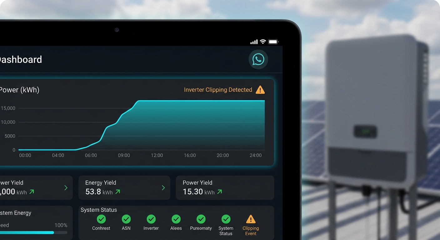
Clipping appears as a distinctive flat-topped power curve in monitoring data. Instead of the typical bell-shaped production profile that follows the sun’s path across the sky, a clipping system shows power rising normally in the morning, reaching the inverter’s maximum capacity, maintaining that flat maximum for a period around solar noon, then declining normally in the afternoon. This characteristic signature makes clipping easy to identify in historical performance data.
Distinguishing clipping from system faults is crucial for proper system management. A flat power curve at the inverter’s rated maximum during peak irradiance hours indicates normal clipping. A flat power curve well below the inverter’s capacity, or occurring during suboptimal conditions, suggests a fault condition such as grid curtailment, inverter derating due to temperature, or array underperformance from shading or soiling.
Setting appropriate alerts and thresholds in monitoring systems prevents alarm fatigue while ensuring real faults are detected. Configure your monitoring platform to recognize expected clipping patterns based on system design and seasonal irradiance variations. Alert thresholds should trigger when performance deviates from expected patterns, for example, if clipping occurs at significantly lower power levels than designed, or if clipping frequency changes dramatically without corresponding weather pattern changes.
AI-powered monitoring systems can automatically learn normal clipping patterns for each installation and flag anomalies that warrant investigation. These intelligent systems distinguish between expected clipping during clear-sky peak production and abnormal power limiting that indicates equipment issues or grid problems. This capability reduces false alarms and helps EPCs manage large installation portfolios efficiently.
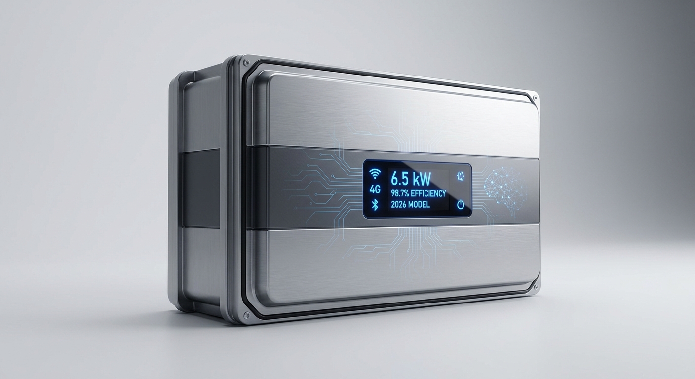
Qbits inverters feature advanced AI-powered WhatsApp monitoring that provides real-time visibility into system performance, including clipping events. The smart monitoring system with Wi-Fi, 4G, and Bluetooth connectivity enables remote tracking of clipping patterns, helping installers verify that systems are performing as designed and quickly identifying any deviations from expected behavior. This level of monitoring transparency builds client confidence and simplifies ongoing system management.
What Are the Differences Between Clipping in On-Grid vs. Hybrid Inverters?
The behavior and implications of inverter clipping differ significantly between on-grid and hybrid inverter configurations, creating distinct design considerations for each system type.
In on-grid inverters, clipping represents a straightforward curtailment of excess DC power during peak production. When the array generates more power than the inverter can convert, the excess energy is simply not converted to AC, it’s lost as a design trade-off for the economic benefits of DC oversizing. The inverter operates at its maximum AC output, feeding power to the grid or local loads, while the MPPT system adjusts to limit DC input to manageable levels.
Hybrid inverters introduce an additional dimension to clipping management through battery charging capability. During periods when DC production exceeds both the inverter’s AC output capacity and current load demand, hybrid systems can potentially divert excess power to battery charging rather than clipping it entirely. This creates an opportunity to capture energy that would otherwise be lost in a pure on-grid configuration.
However, the ability to eliminate clipping through battery charging depends on several factors. Battery state of charge is critical, if batteries are already fully charged during peak production hours, the hybrid inverter still clips excess power just like an on-grid unit. Battery charging rate limitations also matter; if the battery can only accept 10 kW of charging power but you have 15 kW of excess DC production, 5 kW will still be clipped.
Design considerations for hybrid systems in India must account for typical load and production patterns. Commercial installations with high daytime loads might rarely experience clipping in hybrid configurations, as excess production goes to loads and battery charging. Residential systems with low daytime consumption and high evening loads might still experience significant clipping during midday peak production, even with battery storage.
Qbits offers both on-grid and hybrid inverters with battery integration capabilities, providing flexibility for different project requirements. The hybrid inverter line enables sophisticated energy management strategies that can reduce, though not necessarily eliminate, clipping losses while providing backup power and load shifting capabilities. When designing hybrid systems, EPCs should model both clipping losses and battery utilization patterns to optimize the DC-to-AC ratio for maximum system value.
Economic analysis for hybrid systems becomes more complex, as the value of stored energy (used during evening peak rate periods or grid outages) may justify different DC oversizing strategies compared to pure on-grid installations. The ability to capture some clipped energy in batteries might support more aggressive DC oversizing ratios in hybrid configurations.
How Do You Explain Inverter Clipping to Clients?
Effectively communicating the concept of inverter clipping to clients, particularly those without technical backgrounds, is an essential skill for EPCs and solar installers. The key is using clear analogies, visual aids, and focusing on economic outcomes rather than technical details.
A simple analogy that resonates with most clients compares the inverter to a highway. Imagine your solar panels are cars trying to reach their destination (the grid or your loads), and the inverter is the highway they travel on. If you have a four-lane highway (50 kW inverter) but occasionally have enough cars for six lanes (60 kW of solar production), some cars have to wait during peak traffic times. However, having more cars available means that during normal conditions, morning, evening, cloudy days, you’re using all four lanes efficiently instead of having empty lanes. The small amount of “waiting” during peak times is far outweighed by the increased traffic flow during the rest of the day.
Visual aids and graphs make the concept immediately clear. Show clients a side-by-side comparison of power production curves: one showing a perfectly sized system with a bell curve that never reaches the inverter maximum, and another showing an optimally oversized system with a flat-topped curve during peak hours. Highlight that the area under the oversized system’s curve, representing total energy production, is significantly larger despite the flat top.
Emphasizing economic benefits shifts the conversation from technical concerns to business value. Present the analysis in terms clients understand: “By investing in 20% more solar panels instead of a larger inverter, we’ll increase your annual energy production by 14% while only losing 2% to clipping during peak hours. This approach reduces your cost per kilowatt-hour by 10% and improves your return on investment by approximately 15%.” Concrete numbers focused on ROI resonate far more than technical explanations of MPPT algorithms.
Addressing client concerns about “lost” energy requires reframing the conversation. Acknowledge that yes, during a few hours per year, some potential energy is not converted. Then immediately contextualize this: “Those few hours of clipping represent about 2% of annual production, but the larger array captures 14% more energy during the other 8,700 hours of the year. The net result is 12% more total energy and significantly better economics for your investment.”
Presenting ROI analysis that includes clipping considerations provides the complete picture. Show clients the total project cost, annual energy production, energy savings or revenue, and payback period for both a conservatively sized system (no clipping) and an optimally oversized system (2-3% clipping). When clients see that the oversized system delivers better financial performance despite some clipping, concerns typically evaporate.
Communication strategies for EPCs should include preparing standard visual presentations, ROI calculators, and client-friendly explanations of clipping that your sales and technical teams can use consistently. Having these materials ready demonstrates professionalism and builds client confidence in your technical expertise and design decisions.
What Advanced Features Help Manage Inverter Clipping in 2026?
Modern inverter technologies in 2026 incorporate sophisticated features that optimize performance in DC-oversized systems and intelligently manage clipping events. Understanding these advanced capabilities helps EPCs specify the right equipment for optimal system performance.
Multi-MPPT systems represent one of the most effective technologies for reducing clipping in complex installations. Inverters with multiple independent MPPT inputs allow different array orientations, tilts, or panel types to be optimized separately. An east-west array configuration with separate MPPT tracking for each orientation spreads peak production across more hours of the day, reducing the magnitude of clipping events while maintaining high total energy yield. This approach is particularly valuable for commercial rooftops with multiple roof planes or shading constraints.
Smart inverters with dynamic power management capabilities can optimize performance across varying conditions. Advanced algorithms continuously adjust operating parameters based on real-time conditions, maximizing energy harvest while respecting grid requirements and equipment limitations. These intelligent systems can make microsecond-level adjustments to MPPT tracking, reactive power output, and voltage regulation to extract maximum value from oversized arrays.
Weather-responsive clipping strategies represent an emerging capability in premium inverter platforms. By integrating weather forecasting data with system monitoring, intelligent inverters can anticipate high-production periods and adjust operating parameters accordingly. While this doesn’t eliminate clipping, it enables more sophisticated energy management in hybrid systems with storage, potentially shifting battery charging schedules to capture energy that would otherwise be clipped.
Qbits inverters incorporate several advanced features that optimize performance in DC-oversized configurations. The AI-powered monitoring system provides unprecedented visibility into clipping patterns and system performance, enabling data-driven optimization of array configurations and operating parameters. German-grade electronic components ensure reliable operation even during sustained clipping events, maintaining the 98% efficiency that Qbits inverters are known for.
The IP66 weather protection rating of Qbits inverters is particularly relevant for clipping management in India’s challenging climate. Inverters operating at maximum capacity during clipping events generate more heat, making robust thermal management and weatherproofing essential. The IP66 rating ensures that even during sustained peak output in harsh rooftop conditions, high temperatures, dust, monsoon humidity, the inverter maintains optimal performance without derating.
Efficiency ratings become especially important in DC-oversized systems. An inverter that maintains high efficiency across a wide load range, from 20% to 100% of rated capacity, delivers better overall performance in oversized configurations. Qbits inverters maintain their 98% efficiency rating across the full operating range, ensuring that both the additional energy captured through DC oversizing and the power converted during clipping events are handled with minimal losses.
The low start-up voltage capability of modern inverters extends productive hours at the beginning and end of each day, complementing the benefits of DC oversizing. By beginning power conversion earlier in the morning and continuing later in the evening, low start-up voltage maximizes the value of the oversized array during periods when clipping is not a factor.
When evaluating solar inverter manufacturers in India, EPCs should prioritize these advanced features that optimize performance in DC-oversized configurations. The combination of robust hardware, intelligent monitoring, and sophisticated control algorithms separates premium inverters from basic models, delivering superior long-term value for installations designed with strategic clipping.
Conclusion: Optimizing Solar System Design with Strategic Inverter Clipping
Understanding inverter clipping transforms it from a source of concern into a powerful tool for optimizing solar system economics and performance. For EPCs and installers across India, mastering the relationship between DC oversizing and clipping enables better system designs, improved client ROI, and more competitive project proposals.
The key insights from this comprehensive FAQ guide are clear: inverter clipping within the 1-3% annual range is not only acceptable but economically optimal for most installations. By strategically oversizing DC arrays relative to inverter capacity, you capture significantly more energy during the vast majority of operating hours while accepting minimal losses during peak production periods. The net result is higher total energy production, lower levelized cost of energy, and better return on investment for your clients.
Modern inverter technologies, particularly those incorporating multi-MPPT systems, advanced monitoring, and robust thermal management, make DC oversizing strategies more effective than ever. Quality inverters engineered with premium components and comprehensive testing protocols handle clipping events effortlessly, maintaining high efficiency and reliability throughout their operational life.
For solar professionals seeking to optimize their installations with inverters designed for DC-oversized configurations, Qbits offers the advanced features and robust engineering needed for superior performance. With support for up to 100% DC oversizing, AI-powered monitoring, German-grade components, and an industry-leading 12-year warranty, Qbits inverters provide the foundation for optimally designed solar systems that maximize client value.
Ready to optimize your next solar project with strategic inverter clipping and advanced inverter technology? Contact our technical team to discuss your specific project requirements and learn how Qbits inverters can deliver superior performance in DC-oversized configurations. Explore our complete range of on-grid and hybrid inverters engineered for optimal clipping management, or become a Qbits partner to offer your clients the most advanced inverter technology available in the Indian market today.
This blog post was written using thestacc.com