
Solar Inverter Sizing: 12 Critical Questions Answered

Selecting the right inverter capacity is one of the most critical decisions in solar system design. Get it wrong, and you risk reduced energy generation, premature equipment failure, voided warranties, and significant financial losses. For EPCs, installers, and facility owners across India, understanding inverter sizing is essential to maximizing system efficiency, ensuring long-term reliability, and achieving optimal return on investment.
With the rapid evolution of solar technology—particularly the emergence of 750W+ high-wattage panels—traditional sizing rules no longer apply. Modern installations demand a more sophisticated approach that accounts for DC oversizing ratios, temperature derating, regional climate variations, and advanced monitoring capabilities. This comprehensive guide answers the 12 most critical questions about inverter sizing, providing EPCs and installers with the technical knowledge needed to make informed decisions that protect both system performance and client investments.
Why Inverter Sizing Matters for Solar System Performance
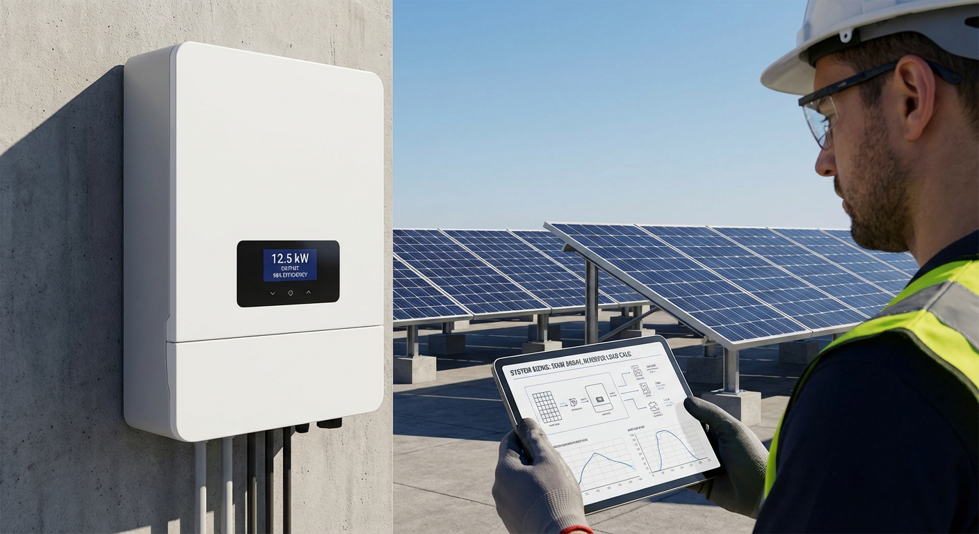
The inverter serves as the heart of any solar power system, converting DC electricity from panels into usable AC power. When properly sized, an inverter operates within its optimal efficiency range, maximizes energy harvest, and delivers reliable performance for 12-15 years or more. However, incorrect inverter sizing creates a cascade of problems that compromise the entire installation.
Undersized inverters lead to power clipping during peak production hours, permanently limiting energy generation and reducing ROI by 10-20% or more. The inverter operates at maximum capacity for extended periods, accelerating component wear and shortening lifespan. Conversely, oversized inverters run inefficiently at low loads, particularly during morning and evening hours when solar production is minimal. This reduces overall system efficiency and increases upfront costs without proportional benefits.
Beyond performance issues, improper sizing can void manufacturer warranties. Most inverter manufacturers, including Qbits, specify maximum DC input limits and oversizing ratios. Exceeding these parameters—even if the system appears to function—may invalidate warranty coverage, leaving installers and facility owners financially exposed when equipment fails. For commercial and industrial installations where inverters represent significant capital investments, this risk is unacceptable.
The financial implications extend throughout the system lifecycle. A poorly sized inverter affects not just immediate energy production but also maintenance costs, replacement timing, and overall project economics. For EPCs managing multiple installations, sizing errors multiply across projects, damaging reputation and client relationships. Understanding the principles of proper inverter sizing is therefore not just a technical requirement—it’s a business imperative.
1. How Do I Calculate the Right Inverter Capacity for My Solar Array?
Calculating inverter capacity begins with understanding your total DC array wattage. Sum the nameplate wattage of all solar panels in your system. For example, a residential installation with 20 panels rated at 540W each produces 10,800W (10.8kW) of total DC capacity. However, this is just the starting point for inverter sizing calculations.
The basic sizing formula applies a DC-to-AC ratio, also called the inverter loading ratio or oversizing ratio. Industry standard practice recommends sizing the inverter between 80-90% of total DC capacity for most installations. Using our 10.8kW example, this suggests an inverter rated between 8.6kW and 9.7kW AC output. A 10kW inverter would be appropriate for this system, providing a DC-to-AC ratio of 1.08:1.
However, several critical factors modify this basic calculation. Temperature derating is essential—solar panels lose efficiency as temperatures rise above 25°C. In India’s hot climate, panels routinely operate at 50-70°C during peak hours, reducing actual output by 10-15% below nameplate ratings. This natural derating allows for higher DC-to-AC ratios without clipping losses.
Location-specific considerations also matter significantly. Sites with partial shading, suboptimal orientation, or high soiling rates will never achieve full nameplate capacity simultaneously across all panels. These real-world conditions justify more aggressive oversizing. Conversely, installations with ideal conditions, perfect south-facing orientation, minimal shading, regular cleaning, should use more conservative ratios to avoid clipping.
For commercial and industrial installations, load profile analysis adds another dimension. If the facility consumes power primarily during peak solar hours, sizing the inverter closer to DC capacity maximizes self-consumption. For export-focused systems selling power to the grid, optimizing for maximum energy harvest across all daylight hours may justify different sizing strategies.
A practical example for a C&I installation: A 100kW DC array (185 panels × 540W) in Mumbai with good orientation but some afternoon shading might use an 85kW inverter, creating a 1.18:1 ratio. This accounts for temperature losses, occasional shading, and soiling while avoiding significant clipping during optimal conditions. The same array in Rajasthan with extreme temperatures and dust might justify a 1.25:1 ratio with an 80kW inverter.
2. What Is DC Oversizing and Why Does It Matter?
DC oversizing refers to installing more solar panel capacity than the inverter’s rated AC output. Expressed as a ratio, a 1.2:1 DC oversizing means 12kW of panels connected to a 10kW inverter. This practice has become standard in modern solar design, driven by economic and performance considerations that make it essential for optimizing inverter sizing decisions.
The primary benefit of DC oversizing is extended energy production during non-peak hours. Solar panels rarely operate at full nameplate capacity except during ideal midday conditions. During morning and evening hours, when irradiance is lower, an oversized array ensures the inverter operates closer to its rated capacity for more hours per day. This significantly increases total daily energy yield, often by 5-15%—without requiring a larger, more expensive inverter.
Temperature derating provides natural headroom for oversizing. As mentioned earlier, panels lose 10-15% efficiency in hot conditions. By oversizing the DC array, you compensate for this loss, ensuring the inverter receives adequate input power even when panels operate below nameplate ratings. In India’s climate, this is particularly important for maintaining consistent performance during summer months when temperatures regularly exceed 40°C.
Industry standards typically recommend DC oversizing ratios between 1.1:1 and 1.3:1 for most installations. Conservative designs use 1.1-1.15:1, suitable for locations with minimal temperature derating and excellent conditions. Standard designs employ 1.2-1.25:1, appropriate for most Indian installations accounting for temperature and real-world losses. Aggressive designs reach 1.3:1 or higher, justified in extreme climates or when maximizing energy harvest is critical.
Qbits inverters support up to 100% DC oversizing capability (2:1 ratio), providing exceptional flexibility for system designers. This allows EPCs to optimize array sizing for specific site conditions without worrying about exceeding inverter limits. The inverters incorporate advanced MPPT algorithms that efficiently manage oversized arrays, preventing damage while maximizing energy harvest. This capability is particularly valuable when working with high-wattage panels where string configurations may naturally result in higher DC-to-AC ratios.
It’s important to note that oversizing beyond manufacturer specifications voids warranties and risks equipment damage. Always verify the maximum DC input voltage, current, and power ratings specified in the inverter datasheet. Proper inverter sizing with appropriate DC oversizing requires balancing energy optimization with equipment protection and warranty compliance.
3. Can My Inverter Handle Modern 750W+ Solar Panels?
The solar industry’s rapid shift toward high-wattage panels, now reaching 750W and beyond, has created compatibility challenges that directly impact inverter sizing strategies. These larger, more powerful modules offer significant advantages in reducing balance-of-system costs and installation time, but they also demand careful attention to inverter specifications and string design.
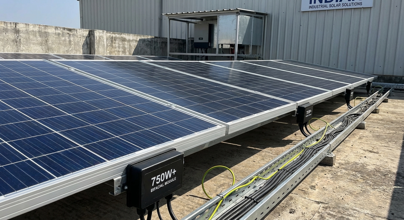
High-wattage panels achieve their increased output through larger physical dimensions and higher voltage ratings. A typical 750W panel might have an open-circuit voltage (Voc) of 50-55V and maximum power point voltage (Vmp) of 42-45V, compared to 40-45V Voc for older 400W panels. This voltage increase affects how many panels can be connected in series without exceeding the inverter’s maximum input voltage, typically 1000V or 1100V for modern inverters.
String configuration becomes more constrained with high-wattage panels. Where you might have connected 22-24 panels of 400W in a single string, 750W panels may limit you to 18-20 panels due to voltage constraints. This affects system design flexibility and may require additional MPPT inputs or parallel strings to accommodate the desired array capacity. Careful calculation of string voltage under all temperature conditions is essential, cold morning temperatures can push Voc significantly higher than nameplate ratings.
Current ratings also require attention. While voltage increases moderately, current ratings of 750W+ panels can reach 13-14A or higher. Verify that your inverter’s maximum input current per MPPT channel can handle these higher currents, especially when designing parallel string configurations. Exceeding current limits risks triggering protective shutdowns or, worse, damaging input circuitry.
Qbits inverters are specifically engineered to support modern 750W+ panels across both residential and commercial product lines. The inverters feature wide MPPT voltage ranges, high current handling capacity, and intelligent algorithms that optimize performance with high-power modules. This future-proof design ensures that EPCs can confidently specify the latest panel technology without compatibility concerns or the need for premature inverter upgrades.
When sizing inverters for 750W+ panels, pay special attention to the DC-to-AC ratio. The higher wattage per panel means fewer panels are needed to reach a given DC capacity, but string voltage constraints may limit configuration options. Work through multiple design scenarios to find the optimal balance between panel count, string configuration, inverter capacity, and DC oversizing ratio. Software tools like PVsyst or Helioscope can help validate designs before procurement.
4. What Happens If I Undersize My Inverter?
Undersizing an inverter, selecting a unit with insufficient AC capacity relative to the DC array, creates immediate and long-term performance problems that undermine system economics. The most visible consequence is power clipping, where the inverter cannot convert all available DC power during peak production hours. The excess energy is simply lost, permanently reducing daily energy yield.
Consider a 15kW DC array connected to an 8kW inverter (1.875:1 ratio). During optimal midday conditions, the panels might generate 14kW after temperature derating, but the inverter can only output 8kW. The remaining 6kW is clipped, wasted energy that could have been captured with proper inverter sizing. Over a year, this clipping can reduce total energy production by 15-25%, directly impacting ROI and extending payback periods.
Beyond lost energy, undersized inverters operate at maximum capacity for extended periods. This sustained high-load operation increases component temperatures, accelerates wear on capacitors and semiconductors, and shortens overall lifespan. An inverter designed for 10-12 year service life might fail in 6-8 years when chronically overloaded. Replacement costs and downtime further erode project economics.
Thermal stress from undersizing also affects efficiency. Inverters operate most efficiently at 30-70% of rated capacity. An undersized unit spends most productive hours at 90-100% capacity, where efficiency drops and heat generation increases. This compounds energy losses beyond simple clipping, reducing overall system performance by several additional percentage points.
There are rare scenarios where intentional undersizing makes economic sense. In locations with extremely high electricity rates during peak hours and time-of-use tariffs, limiting inverter capacity to match peak load demand can optimize self-consumption economics. Some grid-tied systems in areas with export limitations may also intentionally undersize to comply with utility restrictions. However, these are exceptions requiring careful financial modeling, not standard practice.
Warning signs of an undersized inverter include consistent flat-topping of power output curves during midday hours, inverter operating at maximum capacity for 3+ hours daily, and higher-than-expected inverter temperatures. Monitoring systems like Qbits’ AI-powered WhatsApp monitoring can quickly identify these patterns, allowing corrective action before significant energy losses accumulate.
5. What Are the Risks of Oversizing My Inverter?
While undersizing creates obvious problems, oversizing an inverter, selecting a unit with excessive AC capacity relative to the DC array, introduces more subtle but equally problematic inefficiencies. The primary issue is reduced efficiency at low load conditions, which affects performance during the majority of operating hours when solar production is below peak levels.
Inverters achieve peak efficiency at 30-70% of rated capacity. A 10kW inverter operating at 3-7kW delivers its best performance, typically 97-98% efficiency for quality units. However, at loads below 20% of rated capacity, common during morning, evening, and cloudy conditions, efficiency drops significantly, sometimes to 85-90% or lower. An oversized inverter spends more hours in this inefficient range, reducing overall daily energy conversion.
Consider a 5kW DC array connected to a 10kW inverter (0.5:1 ratio). During morning hours when the array produces 1kW, the inverter operates at just 10% capacity with perhaps 88% efficiency, losing 120W. A properly sized 5kW inverter at 20% capacity might achieve 94% efficiency, losing only 60W. These losses accumulate across thousands of operating hours annually, reducing total energy yield by 3-5% or more.
Financial implications extend beyond efficiency losses. Oversized inverters cost more upfront without delivering proportional benefits. A 15kW inverter might cost 40-50% more than a 10kW unit, but if your array only produces 8kW peak, you’re paying for capacity you’ll never use. This increases project costs and extends payback periods without improving performance, poor economics for any installation.
Oversizing can also affect inverter lifespan, though less dramatically than undersizing. Components designed for higher power ratings may experience less thermal stress at lower loads, potentially extending life. However, this benefit rarely justifies the additional cost and efficiency penalties. The optimal approach is right-sizing for the specific application rather than over-engineering for theoretical benefits.
The sweet spot for inverter sizing typically falls between 1.1:1 and 1.3:1 DC-to-AC ratio for most installations. This range balances extended production hours, temperature derating compensation, and efficiency optimization without excessive clipping or low-load inefficiency. Staying within this range, and within manufacturer-specified limits, ensures optimal performance and economics across the system lifecycle.
6. How Do I Match Inverter Sizing to Panel Wattage?
Matching inverter capacity to panel wattage requires more than simple division, it demands careful analysis of string voltage, current characteristics, and MPPT configuration. The goal is ensuring the inverter’s input specifications align with the electrical characteristics of your panel array while optimizing the DC-to-AC ratio for maximum energy harvest.
Start by calculating string voltage under all operating conditions. Multiply the number of panels in series by their Vmp (maximum power point voltage) for normal operating voltage, and by Voc (open-circuit voltage) for maximum voltage. Remember that Voc increases in cold temperatures, apply a temperature coefficient (typically -0.3% per °C) to calculate worst-case cold morning voltage. This maximum voltage must stay below the inverter’s maximum DC input voltage with adequate safety margin.
For example, 18 panels with 45V Vmp and 54V Voc create a string with 810V operating voltage and 972V open-circuit voltage. At -10°C (possible in northern India during winter), Voc might increase to 1,050V. If your inverter has a 1,000V maximum input, this string configuration is unsafe and violates specifications. Reducing to 16 panels keeps maximum cold-weather voltage around 933V, providing adequate safety margin.
Current calculations are equally important. Determine the short-circuit current (Isc) of your panels and verify it doesn’t exceed the inverter’s maximum input current per MPPT channel. For parallel string configurations, multiply Isc by the number of parallel strings. Modern high-wattage panels with 13-14A Isc require careful attention to current limits, especially when designing systems with multiple parallel strings per MPPT input.
MPPT configuration significantly affects inverter sizing optimization. Inverters with multiple MPPT inputs allow independent optimization of different array sections, valuable for installations with multiple orientations, tilt angles, or shading patterns. When matching panel wattage to inverter capacity, consider how many MPPT channels you need and how to distribute strings across them for balanced loading and optimal performance.
A practical example: A 50kW commercial installation using 540W panels (Vmp 41V, Isc 13.2A) might use a 40kW inverter with 4 MPPT inputs. Design four strings of 23 panels each (92 panels total, 49.68kW DC). Each string operates at 943V Vmp, safely below 1,000V limits even in cold conditions. With one string per MPPT input, the system achieves 1.24:1 DC-to-AC ratio, ideal for Indian conditions with temperature derating and optimal energy harvest.
Always consult the inverter datasheet for specific input specifications, including maximum voltage, current per MPPT, total DC power rating, and recommended oversizing limits. Quality manufacturers like Qbits provide detailed technical specifications and design guidelines to help EPCs optimize panel-to-inverter matching for reliable, high-performance installations.
7. Should I Size Differently for On-Grid vs Hybrid Inverters?
On-grid and hybrid inverters serve different functions, which affects inverter sizing strategies and considerations. While both convert DC solar power to AC, hybrid inverters add battery charging and backup power capabilities that introduce additional sizing factors beyond simple solar array matching.
For on-grid inverters, sizing focuses exclusively on optimizing solar energy conversion and grid export. The calculations discussed earlier, DC-to-AC ratios, string configuration, MPPT optimization, apply directly. The goal is maximizing energy harvest across all daylight hours while staying within inverter specifications and grid interconnection requirements. On-grid sizing is relatively straightforward once you understand the principles of DC oversizing and temperature derating.
Hybrid inverter sizing requires additional analysis of load profiles, battery capacity, and backup power requirements. The inverter must handle not just solar input but also battery charging current, discharge current during backup operation, and simultaneous solar generation plus load demand. This creates more complex sizing scenarios that demand careful load analysis.
Start hybrid sizing by analyzing the facility’s load profile, hourly power consumption patterns throughout the day. Identify peak load demand, which determines the minimum inverter AC output capacity needed to power critical loads during backup operation. A facility with 8kW peak demand requires at least an 8kW hybrid inverter, regardless of solar array size. This load-based sizing often differs from solar-optimized sizing, requiring compromise or multiple inverters.
Battery integration adds another dimension. The hybrid inverter must provide adequate charging current to fully charge the battery bank during available solar hours. A 20kWh battery bank requiring 4-5 hour charge time needs 4-5kW of charging capacity. If your solar array produces 10kW peak but the inverter only provides 6kW output, you may not fully utilize solar production during high-generation hours. Sizing must balance solar capacity, battery charging requirements, and load demand.
Qbits offers both on-grid and hybrid inverter solutions, each optimized for their specific applications. The on-grid commercial and industrial inverters focus on maximum solar energy conversion with up to 100% DC oversizing capability and 98% efficiency. The hybrid inverters integrate battery management, backup switching, and load prioritization while maintaining the same high efficiency and quality standards. When selecting between on-grid and hybrid options, consider not just current requirements but also future expansion plans and backup power needs.
For installations where backup power is essential but load demand exceeds solar capacity, consider hybrid inverters with grid-assist functionality. These systems can draw from grid, solar, and battery simultaneously to meet high loads while still providing backup capability during outages. This flexibility allows more aggressive solar array sizing without being constrained by instantaneous load matching requirements.
8. How Does Location and Climate Affect Inverter Sizing in India?
India’s diverse climate zones, from Himalayan cold to Rajasthan heat to coastal humidity, create location-specific challenges that significantly impact inverter sizing decisions. Understanding regional variations in temperature, irradiance, weather patterns, and environmental conditions is essential for optimizing system performance and longevity.
Temperature effects dominate sizing considerations across most of India. Solar panels lose approximately 0.4-0.5% efficiency per degree Celsius above 25°C. In Rajasthan, Gujarat, or central India where summer rooftop temperatures reach 65-70°C, panels operate 40-45°C above standard test conditions, reducing output by 16-22%. This substantial derating allows for more aggressive DC oversizing, ratios of 1.25-1.3:1 are appropriate and won’t cause clipping because panels rarely achieve nameplate capacity.
Conversely, installations in cooler regions like Himachal Pradesh, Uttarakhand, or high-altitude areas experience less temperature derating. Panels operate closer to nameplate ratings, requiring more conservative DC-to-AC ratios around 1.1-1.15:1 to avoid clipping during optimal conditions. Cold morning temperatures also push open-circuit voltage higher, requiring careful string voltage calculations to avoid exceeding inverter limits.
Monsoon patterns affect sizing through reduced irradiance and increased soiling. Coastal regions and areas with heavy monsoon seasons experience 3-4 months of significantly reduced solar production. While this doesn’t directly change inverter sizing calculations, it affects annual energy yield projections and ROI modeling. Systems in high-monsoon areas may justify slightly higher DC oversizing to maximize production during clear-weather months, compensating for monsoon losses.
Dust and soiling rates vary dramatically across India, from minimal coastal areas to extreme desert regions. Heavy soiling can reduce panel output by 15-25% between cleanings, effectively creating natural derating that allows higher DC-to-AC ratios without clipping. However, relying on soiling for derating is poor practice, proper maintenance should minimize soiling losses. Size for clean-panel performance, then benefit from extended inverter life when soiling reduces peak loads.
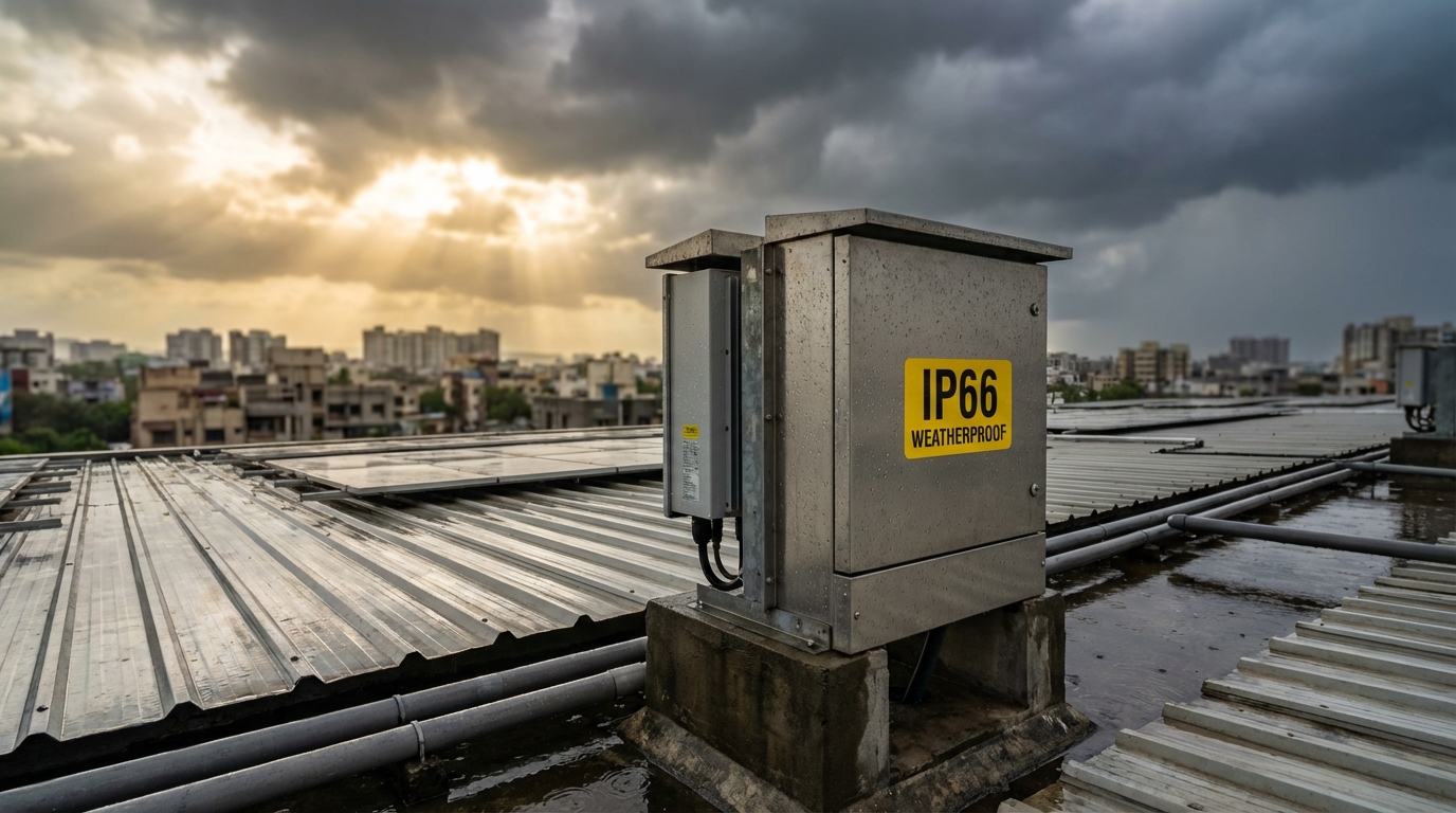
Humidity and coastal salt exposure affect inverter longevity rather than sizing directly, but they’re critical considerations for equipment selection. Qbits inverters feature IP66 weather protection, providing robust defense against dust, rain, and humidity, essential for reliable operation in India’s challenging rooftop environments. This protection ensures that sizing calculations remain valid throughout the inverter’s 12+ year lifespan, without performance degradation from environmental exposure.
Grid stability varies by region and affects inverter requirements. Areas with frequent voltage fluctuations or power quality issues need inverters with wide input voltage ranges and robust surge protection. While this doesn’t change DC array sizing, it affects inverter selection and may influence the decision to include additional protection devices. Qbits inverters incorporate DC and AC surge protection devices (SPDs) as standard, providing comprehensive protection against India’s variable grid conditions.
When sizing inverters for Indian installations, always account for local temperature extremes, seasonal irradiance patterns, and environmental conditions. A one-size-fits-all approach fails to optimize performance, regional customization based on climate data and site-specific analysis delivers superior results and maximizes long-term ROI.
9. What Role Does Inverter Efficiency Play in Sizing Decisions?
Inverter efficiency directly impacts energy yield and system economics, making it a critical factor in inverter sizing decisions. However, understanding efficiency requires looking beyond simple peak efficiency ratings to examine efficiency curves, weighted efficiency metrics, and real-world performance across varying load conditions.
Peak efficiency represents the inverter’s best performance at optimal load conditions, typically 50-70% of rated capacity. Quality inverters like Qbits achieve 98% peak efficiency, meaning only 2% of input power is lost as heat during conversion. However, inverters rarely operate at peak efficiency conditions throughout the day. Morning, evening, and cloudy periods create lower loads where efficiency drops, sometimes significantly.
European efficiency (also called weighted efficiency) provides a more realistic performance metric. This calculation weights efficiency at different load levels, 5%, 10%, 20%, 30%, 50%, and 100%—according to typical operating patterns. A high European efficiency rating (96-97%+) indicates the inverter maintains good performance across all load conditions, not just at peak. When comparing inverters, European efficiency is more valuable than peak efficiency for predicting real-world energy yield.
CEC efficiency (California Energy Commission) uses a similar weighted approach with slightly different load percentages. Both metrics help EPCs compare inverters more accurately than peak efficiency alone. An inverter with 98% peak efficiency but poor low-load performance might deliver less annual energy than a unit with 97.5% peak efficiency but excellent efficiency across all loads.
Efficiency curves show how performance varies across the load range. Quality inverters maintain 95%+ efficiency from 20% to 100% load, with peak efficiency in the 40-70% range. Lower-quality units show steeper efficiency drops at low loads, significantly impacting morning and evening production. When sizing inverters, consider where the unit will operate most frequently, proper sizing ensures the inverter spends maximum time in its high-efficiency range.
This efficiency consideration reinforces proper DC-to-AC ratio selection. An oversized inverter (0.8:1 ratio) spends too much time at low loads where efficiency suffers. An undersized inverter (1.5:1 ratio) operates at maximum capacity where efficiency also drops and clipping occurs. The optimal 1.1-1.3:1 range keeps the inverter in its high-efficiency zone for most operating hours, maximizing energy conversion.
Real-world efficiency differs from rated efficiency due to temperature effects. Inverters lose efficiency as internal temperatures rise, particularly in hot rooftop environments common in India. Quality thermal design with adequate ventilation and heat sinking maintains efficiency even in extreme conditions. Qbits inverters are engineered with German-grade electronic components and advanced thermal management to sustain 98% efficiency across India’s temperature extremes.
When evaluating inverter efficiency for sizing decisions, request detailed efficiency curves and weighted efficiency ratings. Compare performance at 20%, 30%, 50%, and 100% load, not just peak efficiency. Consider how the inverter’s efficiency profile matches your expected load patterns based on array size, location, and DC-to-AC ratio. This analysis ensures your inverter sizing decision optimizes not just capacity but also energy conversion efficiency across all operating conditions.
10. How Do I Account for Future Expansion in Inverter Sizing?
Planning for future system expansion during initial inverter sizing can save significant costs and complexity when facility owners want to add capacity later. However, oversizing for hypothetical future expansion must be balanced against immediate efficiency losses and increased upfront costs. The optimal approach depends on expansion likelihood, timeline, and available space.
The most straightforward expansion strategy uses modular inverter architecture. Instead of installing one large inverter, deploy multiple smaller units that can be supplemented later. For example, a 50kW initial installation might use two 25kW inverters rather than one 50kW unit. When expansion adds another 25kW of panels, simply add a third 25kW inverter. This approach avoids efficiency penalties from oversizing while maintaining expansion flexibility.
DC oversizing headroom provides limited expansion capability within a single inverter. If you initially size at 1.1:1 ratio and the inverter supports up to 1.3:1, you have approximately 18% expansion capacity before exceeding specifications. For a 40kW inverter with 44kW initial array, you could add up to 8kW of panels (52kW total) while staying within 1.3:1 limits. This works for modest expansions but won’t accommodate doubling system size.
String-level expansion requires careful MPPT planning. Ensure your initial design doesn’t fully load all MPPT inputs, leaving capacity for additional strings. An inverter with 4 MPPT inputs might initially use only 3, reserving the fourth for future expansion. This requires running conduit and making provisions for future connections during initial installation, adding these later is expensive and disruptive.
Cost-benefit analysis is essential for expansion planning. Oversizing an inverter by 30% for possible future expansion costs 20-25% more upfront. If expansion is uncertain or more than 3-4 years away, you’re paying a premium for capacity that may never be used while suffering efficiency losses in the interim. If expansion is definite within 1-2 years, the integrated approach may be economical. For uncertain expansion, modular architecture is safer.
Consider technological advancement when planning expansion. Inverter technology, efficiency, and features improve continuously. An inverter purchased today may be outperformed by units available in 3-5 years at similar or lower cost. Oversizing now for future expansion means you’re locked into current technology. Modular expansion allows incorporating newer, better inverters as they become available.
For commercial and industrial installations where expansion is common, discuss future plans explicitly during initial design. If the facility owner has definite expansion plans with timeline and budget, incorporate appropriate headroom. If expansion is speculative, optimize for current requirements and plan for modular additions. Qbits’ range of inverter capacities, from residential to large commercial units, supports flexible expansion strategies without forcing compromises in initial system design.
Document expansion provisions clearly in system design and as-built drawings. Note available MPPT capacity, maximum additional DC input within specifications, conduit provisions for future strings, and recommended expansion configurations. This documentation enables smooth future expansion without reverse-engineering the original design or risking specification violations.
11. What Sizing Mistakes Do EPCs and Installers Most Commonly Make?
Even experienced EPCs and installers make inverter sizing errors that compromise system performance and create warranty issues. Understanding these common mistakes helps avoid costly problems and ensures optimal installations. Here are the most frequent sizing errors encountered in the Indian solar industry.
Ignoring temperature coefficients and derating factors is perhaps the most common mistake. Designers calculate string voltage using nameplate Voc without accounting for cold-weather voltage increase. A string that appears safe at 25°C may exceed inverter limits at 5°C winter mornings, causing shutdowns or damage. Always apply temperature coefficients across the full local temperature range, typically -10°C to +70°C for Indian installations. Similarly, failing to account for temperature derating of panel output leads to undersizing and clipping losses.
Miscalculating string voltage and exceeding inverter limits occurs when designers don’t carefully verify maximum DC input voltage. This is especially problematic with high-wattage 750W+ panels that have higher Voc ratings. Exceeding maximum input voltage, even briefly during cold mornings, can damage input circuitry and void warranties. Always maintain at least 50-100V safety margin below maximum rated input voltage to account for measurement tolerances and extreme conditions.
Overlooking local grid requirements and regulations creates compliance issues. Some utilities limit inverter capacity relative to sanctioned load or impose export restrictions. Sizing an inverter based purely on solar array capacity without verifying grid interconnection requirements can result in rejected installations or forced downsizing after equipment purchase. Always confirm utility requirements before finalizing inverter selection.
Not considering monitoring and surge protection in sizing affects long-term reliability. Some designers focus exclusively on power conversion capacity while neglecting monitoring capabilities and protection features. An inverter without adequate surge protection may fail during India’s frequent lightning storms and grid fluctuations, regardless of proper sizing. Similarly, inadequate monitoring prevents identifying sizing-related performance issues until significant energy losses accumulate. Select inverters with comprehensive monitoring and protection features, like Qbits’ AI-powered WhatsApp monitoring system, as part of the sizing decision.
Using outdated sizing rules for modern high-wattage panels leads to suboptimal configurations. Traditional rules developed for 250-350W panels don’t translate directly to 650-750W modules. The higher voltage and current characteristics require fresh analysis of string configuration, MPPT loading, and DC-to-AC ratios. Don’t simply scale old designs, recalculate from first principles using current panel specifications.
Failing to balance strings across MPPT inputs reduces optimization effectiveness. Unbalanced loading, one MPPT at 8kW and another at 3kW, prevents the inverter from operating optimally. Distribute strings evenly across available MPPT channels, accounting for any orientation or shading differences that might affect production. Balanced loading maximizes efficiency and simplifies troubleshooting.
Neglecting warranty implications of oversizing creates future liability. Exceeding manufacturer-specified DC input limits, even if the system appears to function, voids warranty coverage. When equipment fails, the manufacturer will check installation records and may deny warranty claims for out-of-spec installations. Always stay within published specifications, and document your sizing calculations to demonstrate compliance.
Avoiding these common mistakes requires careful attention to detail, thorough understanding of inverter specifications, and site-specific analysis rather than template-based design. EPCs should develop standardized sizing procedures that incorporate all relevant factors, temperature coefficients, voltage calculations, grid requirements, protection features, and warranty compliance. For guidance on comprehensive inverter selection criteria beyond just sizing, refer to Qbits’ complete EPC selection guide.
12. How Can Smart Monitoring Help Validate My Inverter Sizing Decisions?
Advanced monitoring systems transform inverter sizing from theoretical calculation to validated, data-driven optimization. By tracking real-world performance, monitoring reveals whether your sizing decisions deliver expected results or require adjustment in future projects. This feedback loop continuously improves design accuracy and system performance.
The most obvious monitoring benefit is identifying clipping from undersizing. Power output curves that flat-top during midday hours indicate the inverter cannot convert all available DC power. Monitoring systems display this graphically, showing exactly how much energy is lost and during which hours. This data quantifies the financial impact of undersizing and justifies inverter upgrades or informs sizing decisions for future installations.
Efficiency analysis reveals oversizing problems. If monitoring shows the inverter consistently operating below 30% capacity with reduced efficiency during morning and evening hours, you’ve oversized the system. Comparing actual daily energy yield to theoretical maximum (accounting for irradiance and temperature) reveals the efficiency penalty. This data helps refine DC-to-AC ratio selection for similar future projects.
String-level monitoring identifies configuration issues. If one MPPT input consistently underperforms relative to others, you may have unbalanced string loading, shading issues, or string voltage problems. This granular data helps optimize string configuration and MPPT utilization, critical for maximizing the benefits of proper inverter sizing.
Temperature monitoring validates derating assumptions. By correlating panel temperature with output power, you can verify whether your temperature derating calculations were accurate. If panels consistently operate hotter or cooler than assumed, adjust future sizing calculations accordingly. This is particularly valuable in India’s diverse climate zones where temperature effects vary significantly by region.
AI-powered monitoring takes validation further by automatically identifying performance anomalies and sizing-related issues. Qbits’ AI-powered WhatsApp monitoring system analyzes performance patterns, compares actual output to expected production, and alerts installers to problems like clipping, low efficiency, or string imbalances. This proactive approach catches sizing issues before they accumulate significant energy losses.
Long-term monitoring data builds institutional knowledge for EPCs. By tracking performance across dozens or hundreds of installations with different sizing ratios, locations, and configurations, you develop empirical understanding of what works best in specific scenarios. This data-driven approach replaces guesswork with proven sizing strategies optimized for your typical project types and regions.
Monitoring also validates warranty compliance and protects against future disputes. Detailed performance logs demonstrate that the inverter operated within specifications throughout its life, supporting warranty claims if equipment fails. Conversely, monitoring data showing chronic overloading or out-of-spec operation may explain premature failures and help avoid similar issues in future designs.
For maximum value, implement monitoring from day one of system operation. Don’t wait for problems to arise, proactive monitoring catches sizing issues immediately when corrective action is least expensive. Configure alerts for clipping, low efficiency, and unusual operating patterns. Review monitoring data regularly, not just when problems occur. This disciplined approach transforms monitoring from reactive troubleshooting tool to proactive optimization system.
When selecting inverters, prioritize models with comprehensive monitoring capabilities. Basic monitoring tracks only total output, inadequate for sizing validation. Advanced systems like Qbits’ platform provide string-level data, efficiency analysis, temperature monitoring, and AI-powered insights. This data is invaluable for validating and refining your inverter sizing methodology across all future projects.
Making Informed Inverter Sizing Decisions for Maximum ROI
Proper inverter sizing is both science and art, combining technical calculations with practical experience and site-specific judgment. The 12 questions addressed in this guide provide the foundation for making informed decisions that optimize system performance, maximize energy yield, and ensure long-term reliability for solar installations across India.

The key principles bear repeating: Calculate DC-to-AC ratios between 1.1:1 and 1.3:1 for most installations, accounting for temperature derating and real-world conditions. Verify string voltage and current calculations across all operating temperatures, maintaining adequate safety margins below maximum inverter limits. Match inverter specifications to modern high-wattage panels, ensuring compatibility with 750W+ modules. Balance energy optimization with efficiency, avoiding both undersizing that causes clipping and oversizing that reduces low-load efficiency.
Quality components and comprehensive warranties are equally important as proper sizing. An optimally sized inverter built with inferior components will fail prematurely, negating all sizing benefits. Qbits inverters combine precision inverter sizing flexibility, supporting up to 100% DC oversizing, with German-grade electronic components, 1000+ automated quality tests, and industry-leading 12-year full replacement warranties. This combination ensures that proper sizing delivers sustained performance throughout the system’s operational life.
For EPCs and installers, developing standardized sizing procedures based on the principles in this guide improves consistency and reduces errors across all projects. Document your sizing calculations, maintain records of actual performance through monitoring, and continuously refine your approach based on real-world data. This disciplined methodology builds expertise and reputation while minimizing warranty claims and client issues.
Facility owners investing in solar installations should work with EPCs who demonstrate thorough understanding of inverter sizing principles. Ask about DC-to-AC ratios, temperature derating calculations, string voltage verification, and monitoring capabilities. Verify that proposed inverters support modern high-wattage panels and include comprehensive warranties. Proper sizing is invisible when done correctly, but its impact on energy yield, system longevity, and ROI is substantial and measurable.
The solar industry’s rapid evolution, particularly the shift to high-wattage panels and advanced monitoring systems, demands continuous learning and adaptation. Sizing rules that worked five years ago may not optimize today’s technology. Stay current with manufacturer specifications, industry best practices, and emerging technologies. Leverage resources like comprehensive manufacturer evaluation guides to make informed equipment selections that support optimal sizing strategies.
As India’s solar market continues its explosive growth, the difference between properly sized and poorly sized installations becomes increasingly significant. Millions of solar systems will be installed over the coming years, each representing an opportunity to maximize clean energy generation or a risk of underperformance and premature failure. By mastering inverter sizing principles and selecting quality equipment with appropriate specifications, EPCs, installers, and facility owners can ensure their investments deliver maximum value throughout their operational life.
Ready to optimize your next solar installation with properly sized, high-quality inverters? Explore Qbits’ complete range of on-grid and hybrid inverters engineered for Indian conditions with 100% DC oversizing capability, 750W+ panel support, AI-powered monitoring, and 12-year warranties. For personalized sizing guidance and technical support, connect with our engineering team to discuss your specific project requirements and ensure optimal inverter sizing for maximum ROI.
This blog post was written using thestacc.com