
Solar Inverter Troubleshooting: 15 Common Problems & Expert Solutions (2026)
Solar inverters are the critical heart of any photovoltaic system, converting DC power from panels into usable AC electricity. For solar installation companies, EPCs, and facility owners across India, effective inverter troubleshooting is essential to maintaining system performance, maximizing ROI, and ensuring long-term reliability. When inverter issues arise—whether error codes, connectivity problems, or performance degradation—quick diagnosis and resolution minimize downtime and protect your solar investment.
This comprehensive guide addresses the 15 most common solar inverter problems encountered in Indian installations, providing step-by-step troubleshooting solutions backed by engineering expertise. Whether you’re managing residential on-grid systems or large-scale commercial & industrial installations, understanding these diagnostic procedures will help you resolve issues efficiently and know when to escalate to manufacturer support.
Understanding Solar Inverter Troubleshooting in Indian Installations
The Indian solar market presents unique challenges for inverter operation and maintenance. From extreme temperature variations and monsoon humidity to grid voltage fluctuations and dust accumulation, solar inverters in India must withstand conditions that can accelerate wear and trigger protective shutdowns. Effective inverter troubleshooting begins with understanding these environmental factors and their impact on system performance.

Modern solar inverters incorporate sophisticated monitoring and diagnostic capabilities that enable early problem detection. Advanced features like AI-powered monitoring systems with WhatsApp alerts, Wi-Fi connectivity, and comprehensive data logging transform troubleshooting from reactive repairs to proactive maintenance. For installation companies and facility owners, this means reduced site visits, faster diagnosis, and minimized production losses.
The quality of inverter components directly impacts both reliability and troubleshooting complexity. Inverters built with German-grade electronic components and subjected to rigorous quality testing—such as the 1000+ automated tests performed on each Qbits unit—demonstrate significantly lower failure rates and more predictable behavior when issues do occur. This engineering precision translates to clearer diagnostic patterns and more straightforward resolution paths.
Understanding the relationship between inverter warranty coverage and troubleshooting procedures is equally important. A comprehensive 12-year full replacement warranty provides peace of mind, but proper diagnostic documentation and following manufacturer-recommended troubleshooting steps ensures warranty claims are processed efficiently when component replacement becomes necessary.
1. Inverter Not Turning On or No Display
One of the most alarming scenarios for any solar installation is a completely unresponsive inverter with no display or LED indicators. This problem can stem from multiple causes, ranging from simple connection issues to more serious component failures.
Primary diagnostic steps:
- Verify DC input voltage: Use a multimeter to measure voltage at the DC input terminals. Most inverters require minimum start-up voltage (typically 150-200V for string inverters). If voltage is below threshold, check panel connections, combiner boxes, and string configuration.
- Check AC grid connection: Confirm the AC breaker is in the ON position and grid voltage is present. Inverters will not operate without proper grid connection in on-grid configurations.
- Inspect DC and AC fuses/breakers: Locate and test all protective devices. Blown fuses often indicate overcurrent events or short circuits that require investigation before replacement.
- Examine surge protection devices (SPDs): DC and AC SPDs may have sacrificial elements that fail during lightning or surge events, interrupting power flow to protect the inverter.
- Test auxiliary power supply: Some inverters have separate auxiliary power circuits. Verify these connections are secure and functioning.
If basic checks reveal no obvious issues, the problem may involve internal power supply failure or control board damage. In such cases, document all voltage readings and contact manufacturer support. For inverters with digital warranty systems, having this diagnostic data readily available expedites the support process and potential warranty claims.
2. Grid Voltage or Frequency Error Codes
Grid parameter errors are among the most common inverter troubleshooting scenarios in India, where voltage fluctuations and frequency variations can be significant, particularly in rural and semi-urban areas. Modern inverters continuously monitor grid conditions and disconnect when parameters fall outside acceptable ranges to protect both the inverter and grid infrastructure.
Common grid-related error codes include:
- Over-voltage errors: Typically triggered when grid voltage exceeds 253V (for 230V nominal systems). This often occurs during low-demand periods or in areas with poor grid regulation.
- Under-voltage errors: Activated when voltage drops below approximately 180V, common during peak demand hours or in areas with inadequate grid infrastructure.
- Frequency deviation errors: Indian grid frequency should maintain 50Hz ±0.5Hz. Deviations beyond this range trigger protective disconnection.
- Grid impedance errors: High grid impedance can cause voltage instability, particularly in weak grid areas or at the end of long distribution lines.
Troubleshooting approach:
First, verify that the error is genuine by measuring actual grid parameters with a quality multimeter or power analyzer. If grid voltage or frequency is indeed outside specifications, the inverter is functioning correctly by disconnecting. In such cases, solutions include installing voltage stabilizers, coordinating with utility providers for grid improvements, or implementing hybrid inverter solutions with battery backup to ride through grid disturbances.
If measurements show grid parameters within normal range but errors persist, check grounding quality and AC wiring connections. Poor grounding can cause false voltage readings and erratic inverter behavior. Ensure the grounding resistance is below 5 ohms and all connections are tight and corrosion-free.
For installations experiencing frequent grid-related shutdowns, consider hybrid inverter systems that can operate in multiple modes, providing greater resilience against grid instability while maintaining solar power production.
3. Low Power Output or Reduced Efficiency
Gradual or sudden decreases in power output represent one of the most financially impactful inverter issues, directly affecting system ROI and energy production. Diagnosing reduced efficiency requires systematic analysis of both inverter performance and overall system conditions.
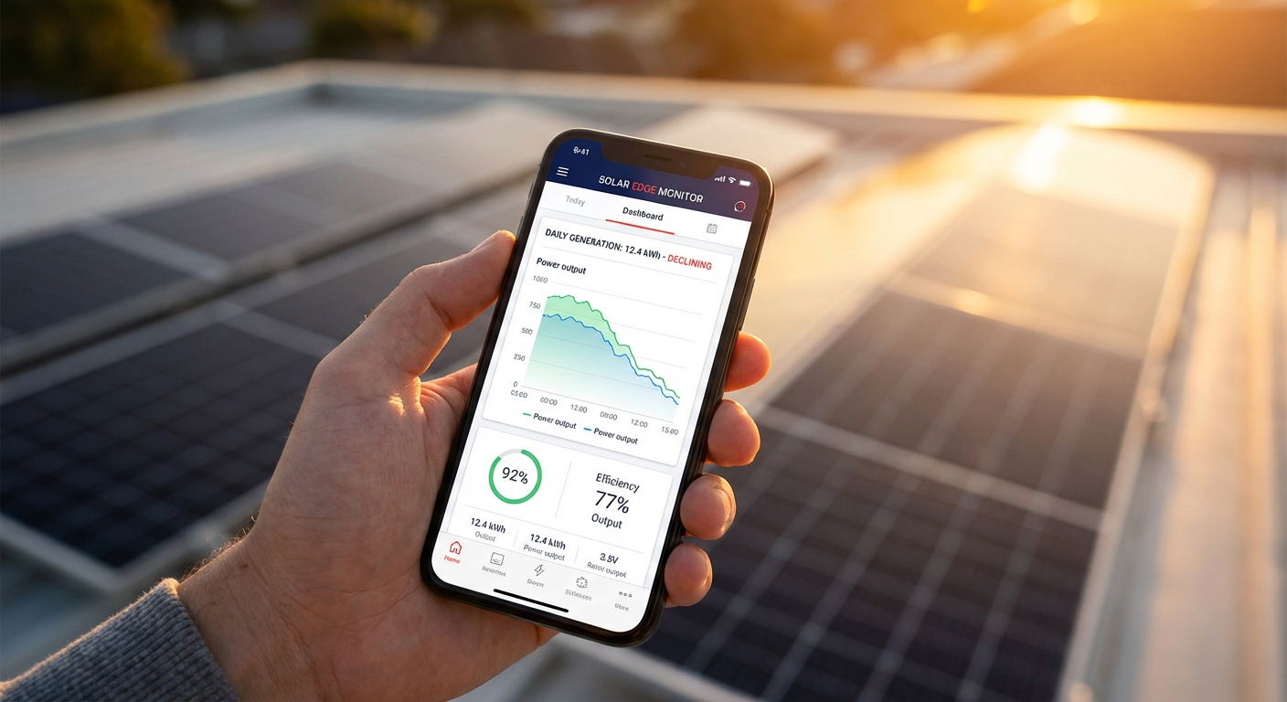
Key diagnostic considerations:
- Panel-level issues: Before focusing on the inverter, verify that solar panels are clean, unshaded, and producing expected voltage and current. Soiling from dust, bird droppings, or pollution can reduce output by 15-30% in Indian conditions. Use monitoring data to compare current production against historical baselines for similar weather conditions.
- String configuration problems: Mismatched panels, incorrect series/parallel connections, or failed bypass diodes can significantly impact DC input to the inverter. Measure voltage and current for each string individually to identify underperforming circuits.
- DC oversizing considerations: While modern inverters support substantial DC oversizing (up to 100% in advanced models), improper configuration can lead to clipping losses or inefficient operation. Verify that your inverter sizing matches the actual panel array capacity.
- Temperature derating: Inverter efficiency naturally decreases at elevated temperatures. In Indian rooftop installations where ambient temperatures exceed 45°C, ensure adequate ventilation around the inverter. Inverters with IP66 weather protection maintain better thermal management in harsh conditions.
- Internal component degradation: Capacitors, cooling fans, and other components can degrade over time, reducing conversion efficiency. Compare current efficiency readings against manufacturer specifications (typically 97-98% for quality inverters).
Advanced diagnostic techniques:
Leverage inverter monitoring systems to analyze performance trends over time. AI-powered monitoring platforms can identify subtle efficiency degradation patterns that might not be immediately obvious through manual inspection. Look for:
- Declining efficiency curves over weeks or months
- Performance variations between similar weather days
- Unusual power factor readings or reactive power consumption
- Inconsistent MPPT (Maximum Power Point Tracking) behavior
For commercial and industrial installations where even small efficiency losses translate to significant revenue impact, establishing performance baselines and conducting quarterly efficiency audits is essential. Document all findings and compare against warranty specifications—inverter efficiency guarantees typically ensure minimum performance levels throughout the warranty period.
4. Inverter Overheating and Thermal Shutdown
Thermal management is critical for inverter longevity and consistent performance, particularly in India’s challenging climate. Most solar inverters incorporate temperature sensors and thermal protection circuits that shut down the unit when internal temperatures exceed safe thresholds, typically around 75-85°C for internal components.
Common causes of overheating:
- Inadequate ventilation: Inverters installed in enclosed spaces, against walls without clearance, or in direct sunlight experience restricted airflow. Maintain minimum clearances as specified in installation manuals—typically 30cm on all sides.
- Cooling fan failure: Many inverters use active cooling fans that can accumulate dust or fail mechanically. Listen for unusual fan noise or absence of airflow during operation.
- Dust accumulation: Indian environments, particularly in northern regions, generate significant dust that clogs cooling fins and ventilation openings. Regular cleaning is essential for thermal management.
- Excessive ambient temperature: Rooftop installations in summer can experience ambient temperatures exceeding 50°C. While quality inverters are designed for these conditions, sustained extreme heat accelerates thermal stress.
- Overloading: Operating inverters consistently at or above rated capacity generates excess heat. Verify that actual load doesn’t exceed inverter specifications.
Resolution strategies:
For immediate thermal shutdown issues, allow the inverter to cool completely before restart. Inspect and clean all ventilation openings, removing dust, debris, and any obstructions. If the inverter is mounted in direct sunlight, consider installing a shade structure that maintains airflow while blocking direct solar radiation.
For recurring overheating problems, evaluate the installation location. Inverters should ideally be mounted in shaded areas with good natural ventilation. In commercial installations, consider climate-controlled equipment rooms for inverter placement, particularly for high-value systems where consistent performance is critical.
The quality of inverter construction significantly impacts thermal performance. Inverters with robust thermal design, quality heat sinks, and weather-resistant enclosures maintain better temperature control. The IP66 weather protection rating ensures sealed construction that protects against dust ingress while maintaining thermal management through intelligent design.
5. Communication and Monitoring Connectivity Issues
Modern solar installations depend on reliable communication between inverters and monitoring platforms for performance tracking, remote diagnostics, and alert notifications. Connectivity problems can leave installation companies and facility owners blind to system performance and emerging issues.
Common connectivity troubleshooting scenarios:
- Wi-Fi connection failures: Verify that the inverter is within range of the Wi-Fi router and that network credentials are correctly configured. Check for network congestion, particularly in commercial buildings with many connected devices. Ensure the router supports 2.4GHz networks, as many inverter Wi-Fi modules don’t support 5GHz bands.
- 4G/cellular connectivity issues: For remote installations using cellular connectivity, verify SIM card activation, data plan status, and cellular signal strength. Poor signal areas may require external antennas or signal boosters.
- Bluetooth pairing problems: Bluetooth typically serves for initial configuration and local monitoring. Ensure Bluetooth is enabled on your mobile device and that you’re within range (typically 10-15 meters). Reset Bluetooth pairing if connection fails repeatedly.
- Server connection errors: If the inverter connects to the network but can’t reach monitoring servers, check firewall settings and ensure required ports are open. Some corporate networks block outbound connections that monitoring systems require.
- Data logging gaps: Intermittent connectivity can create gaps in performance data. Review connection logs to identify patterns—issues occurring at specific times may indicate network congestion or scheduled maintenance windows.
Advanced monitoring features:
Next-generation monitoring systems like AI-powered WhatsApp monitoring provide significant advantages for troubleshooting and system management. These platforms deliver real-time alerts directly to installers and facility managers, enabling immediate response to issues. When evaluating inverter monitoring solutions, prioritize systems that offer:
- Multi-channel connectivity (Wi-Fi, 4G, Bluetooth) for redundancy
- Intelligent alert filtering to reduce notification fatigue
- Historical data analysis for trend identification
- Remote parameter adjustment capabilities
- Secure data transmission and India-based server storage for data sovereignty
For installation companies managing multiple sites, centralized monitoring platforms that aggregate data from all installations streamline troubleshooting and enable proactive maintenance scheduling across your entire portfolio.
6. Ground Fault and Insulation Resistance Errors
Ground fault detection is a critical safety feature in solar inverters, protecting against electrical hazards and fire risks. When inverters display ground fault or insulation resistance errors, immediate investigation is required as these conditions can indicate serious safety issues.
Understanding ground fault mechanisms:
Solar inverters continuously monitor insulation resistance between DC circuits and ground. When this resistance falls below safe thresholds (typically 1 megohm or higher), the inverter disconnects to prevent potential electric shock hazards or fire risks. Ground faults can occur on either the DC (panel) side or AC (grid) side of the system.
Common causes and diagnostic steps:
- Moisture ingress: Water penetration into junction boxes, cable conduits, or panel frames creates conductive paths to ground. This is particularly common during and after monsoon season in India. Inspect all outdoor electrical enclosures for water damage, corrosion, or compromised seals.
- Cable damage: Rodent damage, mechanical stress, or UV degradation can compromise cable insulation. Visually inspect all visible DC and AC cabling, looking for damaged insulation, exposed conductors, or signs of animal activity.
- Panel defects: Manufacturing defects or physical damage to solar panels can create ground faults. Use a megohmmeter to test insulation resistance of individual panels or strings to isolate the faulty component.
- Connector corrosion: Poor-quality connectors or improper installation can allow moisture ingress and corrosion, creating intermittent ground faults. Inspect all MC4 and other DC connectors for corrosion, proper seating, and secure locking.
- Improper grounding: Paradoxically, inadequate system grounding can cause ground fault errors. Verify that all equipment grounding is properly installed with low-resistance connections to the grounding electrode system.
Testing procedures:
To diagnose ground faults systematically, disconnect the inverter from both DC and AC sources. Using a megohmmeter (insulation resistance tester), measure resistance between positive DC bus and ground, then negative DC bus and ground. Readings should exceed 1 megohm, preferably several megohms. If readings are low, isolate individual strings and test separately to identify the faulty circuit.
For AC-side ground faults, inspect the AC disconnect, breaker panel connections, and all AC wiring for damage or improper installation. Verify that neutral and ground are properly separated (not bonded at the inverter) and that all connections are tight and corrosion-free.
Preventive measures include using high-quality, weather-resistant cables and connectors rated for outdoor solar applications, ensuring all junction boxes have proper IP ratings, and conducting annual insulation resistance testing as part of preventive maintenance programs.
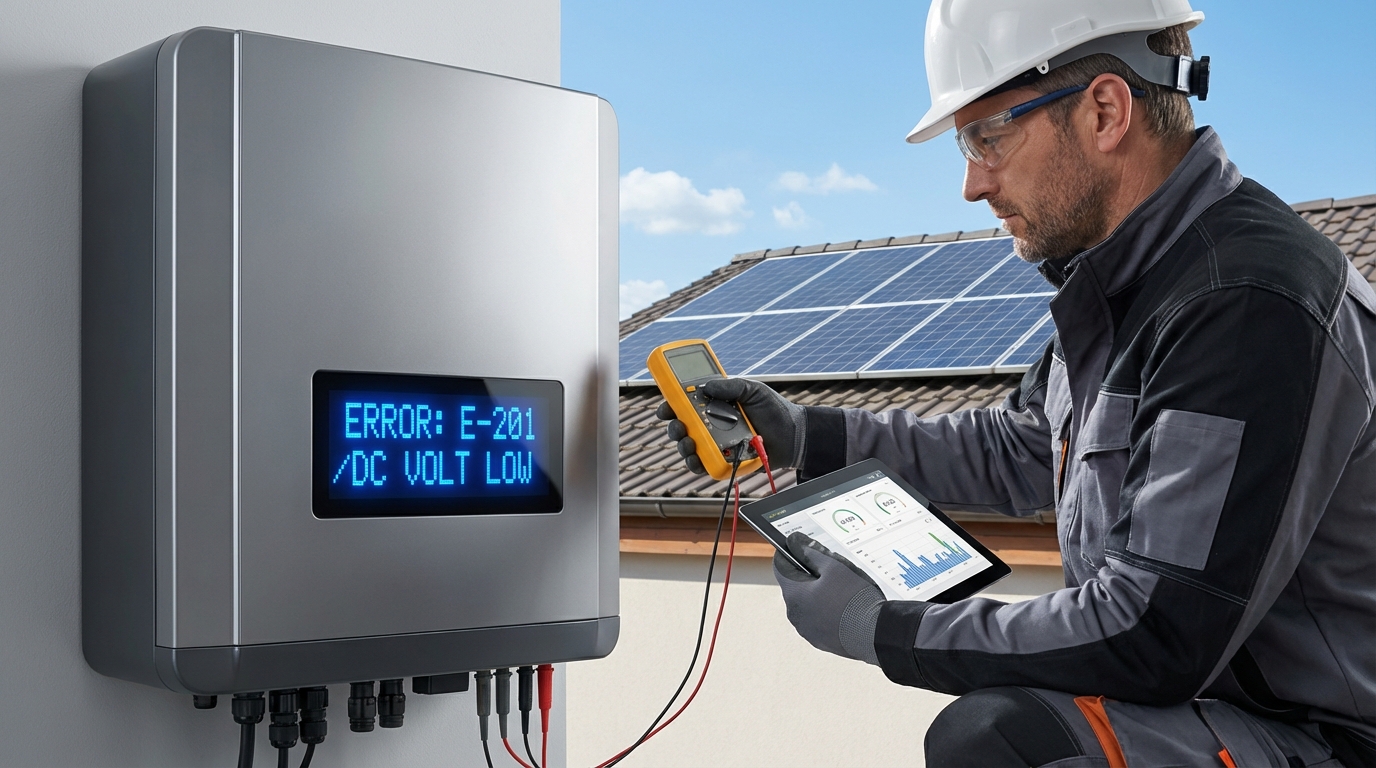
7. DC Overvoltage or String Configuration Errors
DC overvoltage errors occur when the voltage from solar panel strings exceeds the inverter’s maximum input voltage rating. This condition can damage inverter components and typically triggers immediate shutdown to protect the equipment.
Root causes of DC overvoltage:
- Incorrect string configuration: Too many panels connected in series for the inverter’s voltage rating. This is particularly problematic with high-voltage panels (above 40V open-circuit voltage) or when installers fail to account for temperature coefficients.
- Temperature effects: Solar panel voltage increases as temperature decreases. On cold, clear mornings, panel voltage can be 15-20% higher than rated values. String configurations that work fine in summer may trigger overvoltage errors in winter.
- Mismatched inverter selection: Using inverters not designed for the specific panel voltage characteristics. When upgrading to modern high-wattage panels (750W+), verify that existing inverters can accommodate the higher voltages these panels generate.
- Open-circuit conditions: If the inverter disconnects under load but panels remain illuminated, open-circuit voltage (Voc) can exceed maximum power point voltage (Vmp) by 20-25%, potentially triggering overvoltage protection.
Troubleshooting and resolution:
First, calculate the maximum possible string voltage using the panel’s open-circuit voltage specification and the lowest expected ambient temperature for your location. The formula is: Maximum String Voltage = Number of Panels × Voc × (1 + Temperature Coefficient × Temperature Difference). This value must remain below the inverter’s maximum DC input voltage with adequate safety margin (typically 20%).
If calculations reveal overvoltage potential, reconfigure strings by reducing the number of series-connected panels or redistributing panels across multiple inverter inputs. For installations with modern high-wattage panels, ensure your inverter supports these specifications. Advanced inverters with 100% DC oversizing capability and support for panels up to 750W provide greater flexibility in system design.
When selecting inverters for new installations or system expansions, carefully match inverter specifications to panel characteristics. Consider both current voltage ratings and future expansion possibilities. Proper inverter selection based on comprehensive system design prevents costly reconfiguration and ensures optimal performance.
8. Arc Fault Detection and DC Side Safety Issues
Arc fault detection systems protect against one of the most dangerous conditions in solar installations—electrical arcing that can generate extreme heat and potentially cause fires. When inverters display arc fault errors, immediate investigation is critical for safety.
Understanding arc fault conditions:
Arc faults occur when electrical current jumps across a gap in the DC circuit, creating a high-temperature plasma arc. These can result from loose connections, damaged cables, or failed connectors. Modern inverters incorporate arc fault circuit interrupters (AFCI) that detect the characteristic electrical signatures of arcing and shut down the system within milliseconds.
Common arc fault causes:
- Poor connector installation: Improperly crimped or seated MC4 connectors are the leading cause of arc faults. Connectors must be fully engaged and locked to maintain reliable contact under thermal cycling and mechanical stress.
- Cable damage: Cables crushed during installation, damaged by sharp edges, or degraded by UV exposure can develop internal breaks that create arcing conditions.
- Thermal cycling stress: Repeated heating and cooling causes expansion and contraction that can loosen connections over time, particularly in poorly installed systems.
- Corrosion: Moisture ingress into connections creates corrosion that increases resistance and can lead to arcing as current attempts to flow through degraded contacts.
- Component quality: Low-quality connectors, cables, or junction boxes are more prone to failure and arc fault conditions.
Diagnostic procedures:
Arc fault troubleshooting requires careful visual inspection of all DC-side connections. With the system safely de-energized (following proper lockout/tagout procedures), inspect every connector, junction box, and cable termination point. Look for:
- Discoloration or melting around connectors indicating previous arcing
- Loose or improperly seated connectors
- Damaged cable insulation or exposed conductors
- Corrosion on metal contacts
- Signs of overheating such as melted insulation or discolored components
If arc fault errors occur intermittently, they may be related to thermal cycling. Monitor when errors occur—if they happen during temperature transitions (morning warm-up or evening cool-down), thermal expansion/contraction may be stressing marginal connections.
Prevention is far more effective than troubleshooting arc faults. Use only high-quality, BIS/IEC certified components in all installations. Ensure installation teams are properly trained in connector installation techniques and that quality control procedures verify all connections before system commissioning. Regular thermal imaging inspections can identify developing hot spots before they progress to arc fault conditions.
9. Battery Integration Issues in Hybrid Inverters
Hybrid inverters that integrate battery storage add complexity to troubleshooting, as issues can originate from the inverter, battery system, or the communication between them. For facility owners investing in hybrid inverter India solutions for backup power and load shifting, understanding these integration challenges is essential.
Common hybrid system troubleshooting scenarios:
- Battery not charging: Verify battery voltage is within acceptable range for charging. Check BMS (Battery Management System) communication—many hybrid inverters require proper communication with the BMS to enable charging. Inspect battery breakers and fuses, and confirm charging parameters are correctly configured in inverter settings.
- Battery not discharging: Check discharge enable settings and time-of-use programming. Verify that battery state of charge is sufficient for discharge and that discharge current limits are properly configured. Some systems require manual mode changes to enable discharge.
- BMS communication errors: Hybrid inverters communicate with battery systems via CAN bus or RS485 protocols. Verify cable connections, proper termination resistors, and protocol compatibility between inverter and battery. Mismatched communication protocols are a common integration issue.
- Charging/discharging cycle problems: Erratic cycling can indicate incorrect battery capacity settings, improper voltage thresholds, or BMS protection activation. Review all battery-related parameters in the inverter configuration and compare against battery manufacturer specifications.
- Backup mode failures: If the system doesn’t switch to backup mode during grid outages, verify backup mode is enabled, backup loads are properly connected to backup output terminals, and battery capacity is sufficient for the configured loads.
Integration best practices:
Successful hybrid system operation requires careful attention to compatibility and configuration. When specifying hybrid inverters, verify explicit compatibility with your chosen battery system. Generic “lithium battery compatible” specifications may not ensure proper communication and optimal performance.
Document all configuration parameters during commissioning, including battery capacity, voltage ranges, charge/discharge current limits, and communication settings. This documentation proves invaluable during troubleshooting and when updating system firmware or replacing components.
For commercial installations where backup power is critical, implement regular testing of backup mode operation. Scheduled grid disconnect tests verify that the system will perform as expected during actual outages, identifying configuration or integration issues before they impact operations.
10. Weather-Related Failures and Environmental Protection
India’s diverse climate presents significant challenges for solar inverter reliability. From monsoon humidity and flooding to extreme summer heat and dust storms, environmental protection is critical for long-term performance and minimizing troubleshooting requirements.
Monsoon season challenges:
The monsoon period brings multiple risks to solar installations. Heavy rainfall can expose inadequate weatherproofing, causing water ingress into inverters, junction boxes, and cable conduits. Symptoms include ground fault errors, corrosion-related failures, and intermittent operation. Preventive measures include:
- Verifying all enclosures meet appropriate IP ratings (IP65 minimum for outdoor installations, IP66 preferred for harsh conditions)
- Inspecting and resealing cable entry points before monsoon season
- Ensuring proper drainage around ground-mounted equipment
- Installing inverters in locations protected from direct rain exposure when possible
Lightning and surge events increase dramatically during monsoon season. Verify that both DC and AC surge protection devices are properly installed and functional. After severe storms, inspect SPDs for damage and test their continuity—many SPDs have visual indicators showing their operational status.
Dust and pollution impacts:
Northern and western India experience significant dust accumulation that affects both panel output and inverter cooling. Dust infiltration into inverter enclosures can cause overheating, cooling fan failure, and accelerated component degradation. Regular cleaning schedules should include:
- External cleaning of inverter enclosures and ventilation openings
- Panel cleaning to maintain optimal power production
- Inspection of air filters (if equipped) and replacement as needed
- Verification that cooling fans operate freely without dust buildup
Inverters with robust IP66 weather protection provide sealed construction that prevents dust ingress while maintaining thermal management through intelligent heat sink design. This protection level is particularly valuable in harsh Indian rooftop environments where equipment faces direct exposure to dust, rain, and extreme temperatures.
Extreme temperature considerations:
Summer temperatures exceeding 45-50°C on rooftops challenge inverter thermal management. While quality inverters are designed for these conditions, sustained extreme heat accelerates component aging. Implement temperature monitoring and consider seasonal maintenance schedules that include thermal imaging inspections to identify developing hot spots before they cause failures.
Conversely, winter morning cold starts in northern regions can trigger temporary errors as inverters warm up. These typically resolve as ambient temperature increases and don’t indicate problems requiring intervention.
11. Firmware and Software Update Issues
Inverter firmware updates deliver bug fixes, performance improvements, and new features. However, update procedures can occasionally encounter problems that require troubleshooting to resolve.
Common firmware update issues:
- Update failures or interruptions: Power loss or communication interruption during firmware updates can leave inverters in non-functional states. Always ensure stable power supply and reliable communication before initiating updates. For critical installations, schedule updates during low-production periods.
- Version compatibility problems: Some firmware versions may have specific prerequisites or may not be compatible with certain hardware revisions. Always verify compatibility before updating and review release notes for known issues or special instructions.
- Configuration loss: Firmware updates occasionally reset custom configurations to defaults. Document all custom settings before updating and be prepared to reconfigure parameters after the update completes.
- Feature changes: New firmware versions may modify user interface layouts, change parameter names, or alter default behaviors. Review release notes to understand changes and communicate them to system operators.
Safe update procedures:
Follow manufacturer-recommended update procedures precisely. Typically, this involves downloading the correct firmware file, transferring it to the inverter via monitoring app or USB connection, and initiating the update process. Never interrupt power or communication during updates.
For installations with multiple inverters, update one unit first and verify proper operation before updating remaining units. This staged approach prevents fleet-wide issues if problems arise with a specific firmware version.
If an update fails and the inverter becomes unresponsive, consult manufacturer support immediately. Many inverters have recovery procedures that can restore functionality, but these often require specialized tools or procedures that should only be performed by trained technicians or manufacturer service personnel.
Maintain a firmware update log documenting versions installed, dates, and any issues encountered. This history proves valuable for troubleshooting and helps identify patterns if problems develop after updates.
12. Anti-Islanding Protection Activation
Anti-islanding protection is a critical safety feature that prevents inverters from continuing to energize the grid during utility outages. While essential for safety, anti-islanding protection can sometimes cause unexpected disconnections that require troubleshooting.
Understanding anti-islanding requirements:
Indian grid codes require that grid-connected inverters detect utility disconnection and cease power export within specified timeframes (typically 2 seconds). Inverters continuously monitor grid voltage, frequency, and impedance to detect islanding conditions. When detected, the inverter immediately disconnects to prevent energizing isolated grid sections that utility workers may assume are de-energized.
False anti-islanding activation:
Occasionally, inverters may detect islanding conditions when the grid is actually present, causing nuisance disconnections. Common causes include:
- Weak grid connections: High grid impedance in rural areas or at the end of long distribution lines can cause voltage and frequency instability that mimics islanding conditions.
- Large load switching: Sudden connection or disconnection of large loads on the local grid can create transient conditions that trigger anti-islanding protection.
- Multiple inverters on weak grids: When multiple solar systems operate on weak grid infrastructure, their combined interaction can create instability that triggers protection systems.
- Improper parameter settings: Anti-islanding sensitivity parameters set too aggressively can cause false triggering. However, these parameters should only be adjusted by qualified technicians and must remain within regulatory requirements.
Troubleshooting approach:
If anti-islanding protection activates frequently, document the timing and circumstances of each event. Look for patterns—do disconnections occur at specific times of day, during particular weather conditions, or coinciding with known load switching events?
Measure grid quality using a power analyzer over extended periods to capture voltage and frequency variations. If measurements reveal poor grid quality, coordinate with utility providers to address infrastructure issues. In some cases, installing grid support equipment like voltage regulators may be necessary.
For installations where grid quality cannot be improved sufficiently, consider hybrid inverter solutions that can operate in multiple modes, providing continued power production even during grid disturbances by switching to battery-supported operation.
13. Error Code Interpretation and Diagnostic Tools
Modern solar inverters communicate problems through error codes displayed on built-in screens, LED indicators, or monitoring apps. Understanding how to interpret these codes and leverage diagnostic tools is fundamental to effective inverter troubleshooting.
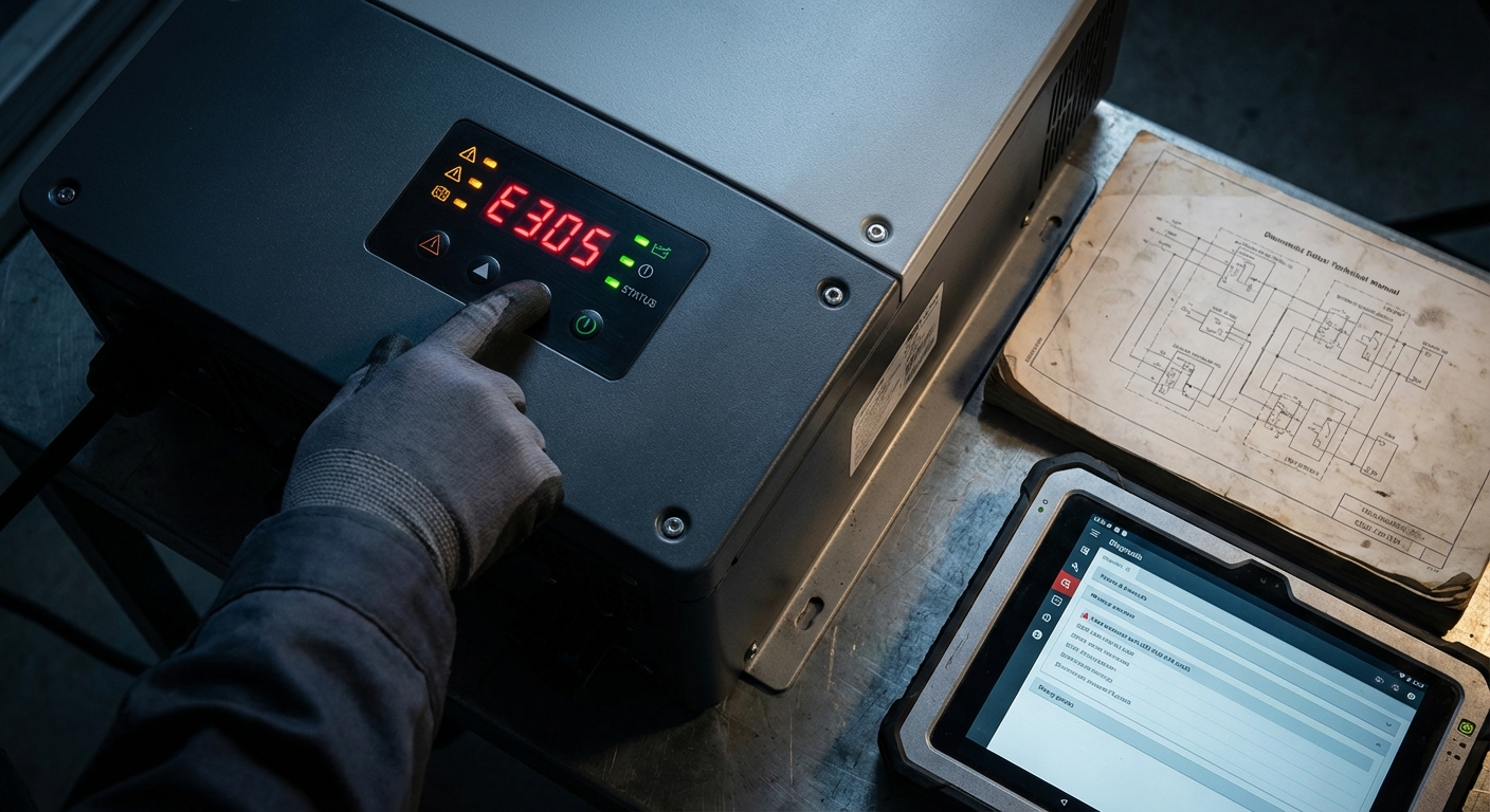
Error code categories:
Most inverter manufacturers organize error codes into categories that indicate the general nature of the problem:
- Grid errors (typically 100-199): Voltage, frequency, or impedance issues related to AC grid connection
- DC input errors (typically 200-299): Problems with solar panel input including overvoltage, undervoltage, or string faults
- Internal errors (typically 300-399): Inverter internal component issues including temperature, fan failure, or control system problems
- Communication errors (typically 400-499): Monitoring and data logging connectivity issues
- Safety errors (typically 500-599): Ground fault, insulation resistance, or arc fault detection
Always consult the specific error code documentation for your inverter model, as code numbering varies between manufacturers. Keep error code reference guides readily accessible for installation teams and maintenance personnel.
Diagnostic tools and techniques:
Effective troubleshooting requires appropriate diagnostic equipment:
- Digital multimeter: Essential for measuring DC and AC voltages, current, and resistance. Invest in quality meters with appropriate voltage ratings for solar applications (typically 1000V DC minimum).
- Clamp meter: Enables non-invasive current measurement on individual strings or AC circuits, useful for identifying imbalanced strings or unexpected current draw.
- Megohmmeter (insulation tester): Required for diagnosing ground faults and verifying insulation resistance. Choose models rated for solar system voltages.
- Thermal imaging camera: Invaluable for identifying hot connections, failing components, or cooling problems before they cause failures. Increasingly affordable models make thermal imaging accessible for routine maintenance.
- Power analyzer: For advanced troubleshooting of grid quality issues, power analyzers capture voltage, frequency, harmonics, and power factor over time.
Leveraging monitoring data:
Modern inverter monitoring systems provide rich diagnostic data beyond simple error codes. Advanced platforms with AI-powered analysis can identify subtle performance degradation patterns, predict potential failures, and provide troubleshooting guidance. When creating support tickets or warranty claims, include:
- Complete error code history with timestamps
- Performance data showing trends before the problem developed
- Environmental conditions (temperature, weather) when errors occurred
- Any recent changes to the system (firmware updates, configuration changes, maintenance performed)
- Photos of error displays and any visible damage or unusual conditions
This comprehensive diagnostic information enables manufacturer support teams to provide faster, more accurate guidance and expedites warranty processing when component replacement is necessary.
14. Preventive Maintenance Best Practices
The most effective inverter troubleshooting strategy is preventing problems before they occur. Implementing systematic preventive maintenance programs significantly reduces failure rates, extends inverter lifespan, and maximizes system ROI.
Recommended maintenance schedule:
Monthly (remote monitoring review):
- Review performance data for anomalies or declining trends
- Verify monitoring system connectivity and data logging
- Check for any error codes or alerts
- Compare production against expected values for weather conditions
Quarterly (visual inspection):
- Visual inspection of inverter exterior for damage, corrosion, or pest activity
- Clean ventilation openings and cooling fins
- Verify cooling fan operation (listen for unusual noise)
- Check all visible connections for tightness and corrosion
- Inspect cable entry points for weatherproofing integrity
- Clean solar panels to maintain optimal power production
Annually (comprehensive inspection):
- Thermal imaging scan of all electrical connections and inverter components
- Insulation resistance testing of DC and AC circuits
- Verification of grounding system integrity and resistance
- Inspection and testing of surge protection devices
- Firmware update review and installation if beneficial
- Detailed performance analysis comparing against baseline data
- Documentation review including warranty status and maintenance history
Seasonal considerations:
Schedule pre-monsoon inspections to verify weatherproofing and drainage before the rainy season. Conduct post-monsoon inspections to identify any weather-related damage. Before summer, verify cooling systems are functioning optimally to handle extreme temperatures.
Quality foundation for reliability:
Preventive maintenance effectiveness depends significantly on initial system quality. Inverters subjected to rigorous quality testing during manufacturing—such as the 1000+ automated quality tests performed on advanced inverters—demonstrate more predictable behavior and lower failure rates. This manufacturing precision translates to fewer surprises during operation and more straightforward troubleshooting when issues do arise.
For installation companies managing multiple sites, implementing standardized maintenance checklists and documentation systems ensures consistent service quality across your portfolio. Digital maintenance management systems can schedule inspections, track findings, and alert you to developing trends across multiple installations.
15. When to Contact Manufacturer Support and Warranty Claims
While many inverter issues can be resolved through systematic troubleshooting, certain situations require manufacturer support or warranty service. Understanding when to escalate and how to prepare for support interactions ensures efficient problem resolution.
Situations requiring manufacturer support:
- Internal component failures: Error codes indicating internal faults, control board issues, or component failures typically require factory service or replacement.
- Persistent unexplained errors: If systematic troubleshooting fails to identify root causes or errors recur after attempted fixes, manufacturer technical support can provide advanced diagnostic guidance.
- Firmware recovery: Failed firmware updates or corrupted software may require specialized recovery procedures only available through manufacturer support.
- Performance degradation beyond specifications: If efficiency or output falls below warranty specifications despite proper maintenance, warranty claims may be appropriate.
- Safety-critical issues: Any situation involving potential safety hazards—unusual odors, visible damage, arcing, or overheating—should be immediately reported to manufacturer support.
Preparing for support interactions:
Effective communication with manufacturer support requires comprehensive information:
- Complete inverter model number and serial number
- Installation date and warranty status
- Detailed description of the problem including when it started and any triggering events
- Complete error code history with timestamps
- Troubleshooting steps already performed and their results
- System configuration details (panel specifications, string configuration, battery details for hybrid systems)
- Photos or videos of error displays and any visible damage
- Performance data showing trends before and during the problem
Warranty claim procedures:
Modern digital warranty systems streamline the claim process, but proper documentation remains essential. For inverters with comprehensive warranty coverage such as 12-year full replacement warranties, understanding claim procedures ensures smooth processing:
- Verify warranty coverage and terms before initiating claims
- Document that the failure occurred within warranty period
- Demonstrate that proper installation and maintenance procedures were followed
- Provide diagnostic data supporting the warranty claim
- Follow manufacturer-specified claim submission procedures
For installation companies, maintaining detailed installation and maintenance records for all projects protects warranty coverage and expedites claims processing. Digital documentation systems that link to manufacturer warranty databases provide the most efficient workflow.
When warranty service requires inverter replacement, coordinate logistics carefully to minimize system downtime. For commercial installations where production losses have significant financial impact, discuss expedited replacement options with manufacturer support.
Qbits provides comprehensive support infrastructure including dedicated technical support teams, service helpdesk, and streamlined warranty claim processes designed to minimize downtime and ensure long-term system reliability.
Maximizing Inverter Lifespan and ROI Through Proactive Troubleshooting
Effective inverter troubleshooting extends far beyond reactive problem-solving. For solar installation companies, EPCs, and facility owners across India, implementing proactive diagnostic strategies and preventive maintenance programs directly impacts system ROI, customer satisfaction, and long-term business success.
The business case for troubleshooting expertise:
Installation companies that develop strong troubleshooting capabilities differentiate themselves in competitive markets. Rapid problem resolution minimizes customer downtime, reduces warranty claims, and builds reputation for reliability. For facility owners, in-house troubleshooting expertise reduces dependence on external service providers and enables faster response to production issues.
The financial impact of effective troubleshooting is substantial. Consider a 100kW commercial installation producing 150,000 kWh annually. Even a single day of downtime represents approximately 410 kWh of lost production. At typical commercial electricity rates, this translates to ₹3,000-4,000 in lost savings per day. Rapid troubleshooting that reduces downtime from days to hours delivers immediate financial returns.
Building troubleshooting competency:
For installation companies, invest in training programs that develop troubleshooting skills across your technical teams. Key competencies include:
- Understanding inverter operating principles and common failure modes
- Proficiency with diagnostic tools and measurement techniques
- Systematic troubleshooting methodologies that efficiently isolate problems
- Familiarity with monitoring platforms and data analysis
- Knowledge of when to escalate to manufacturer support
Maintain technical libraries with error code references, troubleshooting guides, and manufacturer documentation for all inverter brands in your installation portfolio. Digital knowledge bases that technicians can access via mobile devices in the field improve troubleshooting efficiency.
Leveraging technology for proactive management:
Advanced monitoring systems transform troubleshooting from reactive to proactive. AI-powered monitoring platforms analyze performance patterns, identify anomalies before they cause failures, and provide predictive maintenance recommendations. For installation companies managing multiple sites, centralized monitoring enables efficient resource allocation and proactive intervention.
Features like WhatsApp monitoring deliver real-time alerts directly to responsible personnel, enabling immediate response regardless of location. This immediate notification capability is particularly valuable for commercial installations where production losses have significant financial impact.
Selecting inverters for long-term reliability:
Troubleshooting requirements correlate directly with inverter quality and design. When specifying inverters for new installations, consider factors that impact long-term reliability and troubleshooting complexity:
- Component quality: Inverters built with premium components like German-grade electronics demonstrate lower failure rates and more predictable behavior.
- Manufacturing quality control: Rigorous testing during production identifies potential issues before deployment. Inverters subjected to comprehensive quality testing show significantly lower field failure rates.
- Environmental protection: Robust weatherproofing (IP66 rating) prevents environmental damage that causes many common failures.
- Warranty coverage: Comprehensive long-term warranties (12-year full replacement) provide financial protection and demonstrate manufacturer confidence in product reliability.
- Support infrastructure: Manufacturers with strong technical support, readily available documentation, and efficient warranty processes minimize troubleshooting burden.
Qbits inverters incorporate these reliability factors—German-grade components, 1000+ quality tests per unit, IP66 weather protection, and 12-year warranties—specifically designed to minimize troubleshooting requirements and maximize long-term performance in challenging Indian conditions.
Strategic partnerships for success:
For installation companies and distributors, partnering with manufacturers that provide comprehensive support infrastructure enhances your troubleshooting capabilities and customer service quality. Look for manufacturers offering:
- Responsive technical support with India-based teams understanding local conditions
- Comprehensive training programs for installation and troubleshooting
- Digital tools for warranty management and support ticket tracking
- Regular product updates and technical bulletins
- Collaborative approach to resolving complex issues
For businesses interested in expanding their solar product portfolio with reliable, well-supported inverters, explore partnership opportunities with manufacturers that prioritize long-term relationships and mutual success.
Taking action:
Whether you’re an installation company seeking to enhance service capabilities, a distributor evaluating product lines, or a facility owner managing solar assets, investing in troubleshooting expertise and selecting quality equipment delivers measurable returns through reduced downtime, lower maintenance costs, and improved system performance.
For detailed information about inverter specifications, monitoring capabilities, and support infrastructure, explore Qbits product offerings. Technical questions or specific troubleshooting support needs can be addressed through the contact support team, or for immediate assistance, reach out via WhatsApp.
The solar industry in India continues to grow rapidly, driven by favorable policies, declining costs, and increasing energy demand. Success in this expanding market requires not just quality installations, but the expertise to maintain and troubleshoot systems effectively throughout their 25+ year lifespan. By implementing the troubleshooting strategies outlined in this guide and partnering with manufacturers committed to long-term reliability, you position your business and installations for sustained success in India’s solar future.