
Solar Inverter Installation in India: Complete Process Guide & Best Practices (2026)

Solar inverter installation in India has evolved significantly in 2026, with advanced technologies and stringent quality standards transforming how solar power systems are deployed across residential and commercial sectors. As India accelerates toward its renewable energy targets, proper inverter installation has become critical for maximizing system performance, ensuring long-term reliability, and achieving optimal return on investment. This comprehensive guide walks you through the complete inverter installation process, from initial site assessment to post-installation monitoring, while addressing the unique challenges of Indian environmental conditions and regulatory requirements.
Whether you’re a solar installation company, EPC contractor, or facility owner planning a solar project, understanding the intricacies of inverter installation in India ensures your system operates at peak efficiency while meeting BIS/IEC compliance standards. With modern inverters supporting high-wattage panels up to 750W and featuring advanced monitoring capabilities, the installation process demands technical precision and adherence to best practices.
Understanding Solar Inverter Installation Requirements in India
The landscape of solar inverter installation in India has matured considerably, driven by technological advancements and increasing awareness of quality standards. Proper installation is not merely about connecting wires—it’s a systematic process that directly impacts system efficiency, inverter lifespan, and overall project ROI. Studies indicate that improper installation can reduce system efficiency by 15-25% and significantly shorten equipment lifespan, making professional installation practices essential.
In India, inverter installation must comply with BIS (Bureau of Indian Standards) and IEC (International Electrotechnical Commission) standards, which govern safety, performance, and grid connectivity requirements. These regulations ensure that installations meet minimum safety thresholds and maintain grid stability, particularly important as distributed solar generation increases across the country.
The choice between on-grid and hybrid inverters significantly influences installation complexity. On-grid systems require precise grid synchronization and net metering compliance, while hybrid inverters add battery integration complexity, requiring additional safety protocols and charge controller configuration. Modern hybrid inverters with AI-powered monitoring capabilities offer enhanced flexibility but demand more sophisticated installation procedures.
Indian climate conditions present unique installation challenges: extreme temperature variations (from sub-zero in northern regions to 45°C+ in summer), high humidity during monsoons, dust accumulation in arid zones, and coastal salt corrosion. These factors necessitate careful consideration of IP66 weather protection, proper ventilation, and robust mounting solutions that can withstand environmental stress over 25+ year system lifespans.
1. Pre-Installation Site Assessment and Planning
A thorough site assessment forms the foundation of successful inverter installation. This critical first step identifies potential challenges, determines optimal equipment placement, and ensures the installation meets both technical and regulatory requirements. For solar installation companies and EPCs, a comprehensive site survey minimizes costly rework and ensures smooth project execution.
Begin by evaluating the electrical infrastructure at the installation site. Assess the existing electrical panel capacity, available breaker spaces, and grid connection quality. For commercial and industrial installations, verify three-phase power availability and voltage stability. Document the distance between the solar array and proposed inverter location, as excessive cable runs can introduce voltage drops and efficiency losses.
The mounting location selection requires careful consideration of multiple factors. Indoor installations offer better protection from environmental elements but require adequate ventilation to manage heat dissipation. Outdoor installations, common in rooftop commercial projects, must account for direct sun exposure, rain protection, and accessibility for maintenance. The ideal location provides:
- Protection from direct sunlight and rain while maintaining ambient temperature below 40°C
- Adequate clearance on all sides (minimum 30cm) for heat dissipation and service access
- Proximity to both DC input from solar panels and AC output to the grid or load center
- Structural integrity to support inverter weight plus mounting hardware
- Accessibility for installation, commissioning, and future maintenance activities
Site Survey Checklist
Professional installers should document the following parameters during site assessment:
Electrical Parameters:
- Grid voltage and frequency measurements over 24-hour period
- Voltage fluctuation range and power quality assessment
- Available fault current and short circuit capacity
- Earthing system type and ground resistance values
- Existing surge protection infrastructure
Structural Assessment:
- Wall or mounting surface load-bearing capacity
- Material composition (concrete, brick, metal) and condition
- Exposure to environmental elements (sun, rain, wind)
- Vibration sources or structural movement concerns
Environmental Factors:
- Ambient temperature range throughout the year
- Humidity levels and monsoon exposure
- Dust accumulation patterns and air quality
- Proximity to corrosive environments (coastal, industrial)
For installations involving modern high-efficiency inverters that support up to 100% DC oversizing and panels rated at 750W or higher, verify that the selected inverter model matches the total DC capacity and voltage range of the solar array. Undersizing or mismatched specifications can lead to clipping losses or system underperformance.
Documentation requirements vary by state and utility, but typically include electrical single-line diagrams, site layout plans, equipment specifications, and net metering applications. Securing necessary permits before installation prevents project delays and ensures regulatory compliance.
2. Electrical Requirements and Safety Preparations
Proper electrical preparation is paramount for safe and efficient inverter installation. Understanding voltage requirements, implementing surge protection, and establishing robust grounding systems protects both equipment and personnel while ensuring optimal system performance.
Indian grid voltage typically operates at 230V single-phase or 415V three-phase, with frequency at 50Hz. However, voltage fluctuations are common, particularly in rural and semi-urban areas where grid stability may be compromised. Modern inverters with wide input voltage ranges (typically 140-270V for single-phase) can accommodate these variations, but proper surge protection devices (SPDs) remain essential.
Install DC surge protection on the solar array side to protect against lightning strikes and switching transients. DC SPDs should be rated for the maximum system voltage and current, with appropriate voltage protection levels (VPL). Similarly, AC surge protection on the grid side safeguards against utility-side voltage spikes and switching surges. Quality inverters incorporate built-in surge protection, but external SPDs provide additional layers of defense, particularly important in lightning-prone regions.
Earthing and grounding must comply with IS 3043 standards for electrical installations. Establish a dedicated earth pit with resistance below 5 ohms (preferably below 2 ohms for sensitive electronic equipment). Connect all metallic components—inverter chassis, mounting structures, cable trays, and equipment enclosures—to the earthing system using appropriate gauge copper conductors. Proper earthing provides:
- Personnel safety by providing a low-resistance path for fault currents
- Equipment protection against voltage surges and lightning strikes
- System stability by establishing a common reference potential
- EMI reduction by minimizing electromagnetic interference
Cable sizing directly impacts system efficiency and safety. Undersized cables introduce resistive losses, voltage drops, and potential fire hazards. Calculate cable sizes based on maximum current capacity with appropriate derating factors for temperature, bundling, and installation method. For DC cables, use solar-rated cables with UV resistance and appropriate insulation voltage ratings (typically 1000V or 1500V). AC cables should meet IS 694 standards with appropriate current-carrying capacity.
Install isolators and circuit breakers on both DC and AC sides to enable safe disconnection during maintenance or emergencies. DC isolators should be rated for DC voltage and current with appropriate breaking capacity. AC circuit breakers must match the inverter output current with suitable short-circuit breaking capacity.
Safety equipment preparation includes:
- Personal protective equipment: insulated gloves, safety glasses, hard hats
- Insulated tools rated for working voltage
- Voltage testers and multimeters for verification
- Lockout/tagout devices for isolation procedures
- Fire extinguishers (CO2 or dry powder type) suitable for electrical fires
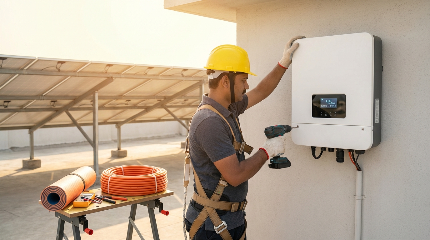
3. Inverter Mounting and Physical Installation
The physical mounting of the inverter sets the stage for long-term reliability and performance. Proper mounting ensures adequate heat dissipation, protects against environmental stress, and provides safe access for maintenance—all critical factors for maximizing inverter lifespan in challenging Indian conditions.
Select a mounting location that balances protection and ventilation. Inverters generate heat during operation, with efficiency losses converted to thermal energy. Modern high-efficiency inverters operating at 98% efficiency still dissipate 2% of processed power as heat—for a 10kW inverter, this amounts to 200W of heat that must be managed. Inadequate ventilation can cause thermal derating, reducing output capacity and accelerating component degradation.
Maintain minimum clearances as specified by the manufacturer, typically:
- Top clearance: 50cm minimum for heat rise and service access
- Side clearances: 30cm on each side for air circulation
- Bottom clearance: 30cm from ground or floor level
- Front clearance: 100cm for safe operation and maintenance access
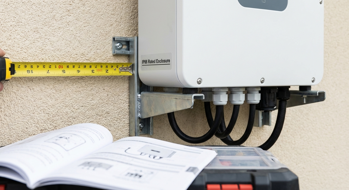
For rooftop installations common in commercial and industrial projects, ensure the inverter mounting location provides IP66 weather protection compliance. This rating ensures complete dust ingress protection and protection against powerful water jets—essential for surviving Indian monsoons and rooftop cleaning operations. If the inverter lacks integrated weather protection, install it within a weatherproof enclosure with adequate ventilation louvers.
Wall mounting procedures require attention to structural integrity:
- Mark mounting points using the inverter mounting template or measuring from the unit’s mounting brackets
- Verify wall strength can support 3-4 times the inverter weight to account for dynamic loads
- Drill mounting holes using appropriate drill bits for the wall material (masonry, concrete, or metal)
- Install anchor bolts or expansion anchors rated for the load and wall type
- Mount the inverter bracket ensuring level installation using a spirit level
- Secure the inverter to the bracket with appropriate fasteners and torque specifications
- Verify stability by applying gentle pressure to ensure no movement or flexing
For ground-mounted or floor-standing installations, use vibration-dampening mounts if the location experiences mechanical vibrations from nearby equipment. Secure cable entry points with weatherproof glands and maintain proper cable bend radius to prevent conductor damage.
Consider future accessibility when finalizing the mounting location. Installers and maintenance personnel need safe access to the inverter display, connection terminals, and internal components. Avoid locations requiring ladders or scaffolding for routine monitoring, as this discourages regular inspection and increases safety risks.
4. DC and AC Wiring Connections
Electrical connections represent the most critical phase of inverter installation, where precision and attention to detail directly impact system safety and performance. Improper wiring can lead to efficiency losses, equipment damage, or serious safety hazards including fire and electric shock.
DC input wiring connects the solar array to the inverter’s DC terminals. Modern installations often involve multiple strings of high-wattage panels, requiring careful attention to polarity, string configuration, and current capacity. Before making any connections:
- Verify all DC isolators are in the OFF position
- Measure open-circuit voltage (Voc) of each string to ensure it falls within the inverter’s input voltage range
- Confirm string polarity using a multimeter to prevent reverse connection damage
- Inspect cable insulation for damage or degradation
When connecting DC cables, follow the inverter manufacturer’s terminal layout carefully. Most modern inverters feature clearly labeled positive and negative terminals with color coding (red for positive, black for negative). Strip cable insulation to the specified length—typically 8-10mm—to ensure adequate contact without exposing excessive bare conductor. Insert cables fully into terminals and tighten to the specified torque value, usually 2.5-3.5 Nm for residential inverters and higher for commercial units.
For systems with DC oversizing up to 100%, verify that the total short-circuit current (Isc) from all strings does not exceed the inverter’s maximum DC input current rating. DC oversizing allows the system to reach rated capacity even during suboptimal conditions, but requires careful calculation to prevent overcurrent conditions during peak production.
Install DC surge protection devices between the solar array and inverter if not already integrated. Connect SPD terminals to the DC positive and negative buses, with the grounding terminal connected to the earthing system. Verify SPD indicator lights show normal operation status.
AC output wiring connects the inverter to the grid connection point or load center. For on-grid systems, this connection must meet utility interconnection requirements and enable proper net metering functionality. Key considerations include:
- Use appropriately sized AC cables based on inverter maximum output current
- Maintain proper phase sequence for three-phase inverters (R-Y-B)
- Install AC circuit breaker with appropriate breaking capacity
- Ensure neutral and earth connections are properly terminated
- Verify AC voltage and frequency match grid parameters before connection
For hybrid inverters with battery integration, additional DC connections to the battery bank require careful attention to battery voltage, capacity, and charge/discharge current ratings. Follow manufacturer specifications for battery cable sizing and fusing requirements. Ensure battery communication cables (typically CAN bus or RS485) are properly connected to enable intelligent charge management.
Cable management significantly impacts installation quality and longevity. Use appropriate cable trays, conduits, or cable ties to secure and organize wiring. Maintain separation between DC and AC cables to minimize electromagnetic interference. Protect outdoor cable runs with UV-resistant conduits and weatherproof all entry points with cable glands rated for the environmental conditions.
Apply proper torque to all terminal connections using a calibrated torque wrench. Under-tightened connections can lead to high resistance, heating, and potential fire hazards. Over-tightening can damage terminals or strip threads. Document torque values applied to critical connections for quality assurance records.
5. Smart Monitoring System Setup and Configuration
Modern inverter installations in 2026 are incomplete without proper monitoring system configuration. Advanced monitoring capabilities transform solar installations from passive power generators into intelligent, self-diagnosing systems that maximize uptime and enable proactive maintenance. For solar installation companies and facility owners, robust monitoring systems provide visibility into system performance and rapid issue identification.
Contemporary inverters offer multiple connectivity options: Wi-Fi, 4G cellular, and Bluetooth, each with specific use cases. Wi-Fi connectivity works well for residential and small commercial installations with reliable internet access. Configure Wi-Fi by accessing the inverter’s setup interface through its temporary access point, then connecting it to the site’s wireless network. Ensure the router provides adequate signal strength at the inverter location and configure firewall settings to allow monitoring data transmission.
For remote or rural installations where Wi-Fi is unavailable or unreliable, 4G connectivity provides independent internet access. Insert a data-enabled SIM card into the inverter’s communication module and configure APN settings according to the cellular provider’s specifications. 4G monitoring ensures continuous data transmission regardless of site internet infrastructure, critical for commercial installations requiring guaranteed uptime visibility.
Bluetooth connectivity enables local monitoring and configuration using mobile devices within range. This proves valuable during commissioning and troubleshooting when direct access to inverter parameters is needed without relying on cloud connectivity.
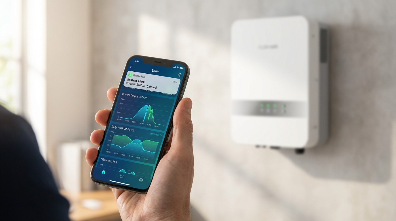
AI-powered monitoring systems represent the cutting edge of solar system management in 2026. These intelligent platforms analyze performance data in real-time, comparing actual output against expected production based on weather conditions, historical patterns, and system specifications. Machine learning algorithms identify anomalies that might indicate developing issues—such as gradual efficiency degradation, string underperformance, or component stress—enabling preventive maintenance before failures occur.
Configure WhatsApp monitoring integration to receive instant alerts and system updates through the familiar messaging platform. This innovative approach to system notifications ensures that installers, facility managers, and system owners receive critical alerts immediately without requiring dedicated monitoring apps or constant dashboard checking. Set up alert thresholds for:
- System offline or communication loss
- Production below expected levels
- Grid voltage or frequency deviations
- Inverter temperature warnings
- Fault codes or error conditions
- Daily production summaries and performance reports
Mobile app installation and configuration provides comprehensive system visibility. Download the manufacturer’s monitoring app and create an account using the inverter serial number and registration code. Configure user permissions appropriately—installers may need full access for configuration and troubleshooting, while end-users require view-only access to production data and system status.
Set performance parameters and alert thresholds based on system specifications and site conditions. Configure expected production ranges accounting for seasonal variations, shading patterns, and local weather conditions. Overly sensitive alerts create notification fatigue, while insufficiently sensitive thresholds may miss important issues.
For installations in India, verify that monitoring data is stored on India-based servers to ensure data security and compliance with data localization requirements. This consideration is particularly important for commercial and industrial installations handling sensitive operational data.
Document all monitoring system credentials, including Wi-Fi passwords, app login information, and installer access codes. Provide this documentation to the system owner along with training on how to access and interpret monitoring data. Clear documentation ensures that system owners can maintain visibility into their investment long after installation completion.
6. System Commissioning and Testing
Commissioning transforms a physically installed system into an operational solar power plant. This systematic process verifies that all components function correctly, safety systems operate as designed, and the system meets performance specifications. Thorough commissioning prevents future issues and provides documented evidence of proper installation.
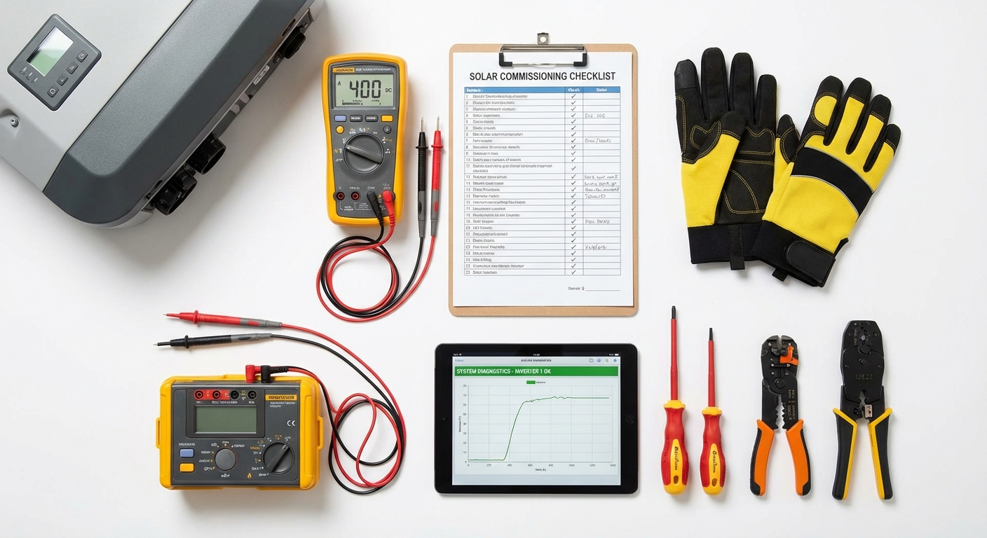
Pre-commissioning safety checks must be completed before energizing the system:
- Verify all electrical connections are tight and properly terminated
- Confirm DC and AC isolators are accessible and properly labeled
- Check earthing continuity and measure earth resistance
- Inspect for any loose hardware, exposed conductors, or physical damage
- Verify surge protection devices are properly connected and operational
- Ensure adequate clearances and ventilation around the inverter
- Confirm all warning labels and safety signage are in place
The initial power-up sequence follows a specific order to prevent equipment damage:
- Close DC isolator to energize the inverter’s DC input. The inverter should power up and display initialization messages
- Verify DC voltage and current readings match expected values from the solar array
- Check inverter display for any fault codes or warning messages
- Close AC isolator to connect the inverter to the grid or load
- Monitor grid synchronization as the inverter detects grid parameters and begins power export
- Observe initial power output and verify it corresponds to available solar irradiance
Testing inverter efficiency and performance requires measuring both DC input and AC output power under various load conditions. Modern inverters achieve 98% efficiency at rated capacity, with slightly lower efficiency at partial loads. Use calibrated power meters to measure:
- DC input voltage and current from each string
- AC output voltage, current, and power factor
- Conversion efficiency at different power levels
- Harmonic distortion levels (should be below 5% THD)
For on-grid systems, verify proper grid synchronization by monitoring voltage, frequency, and phase angle. The inverter should seamlessly synchronize with grid parameters and maintain synchronization under varying load conditions. Test anti-islanding protection by simulating grid disconnection—the inverter should cease power export within 2 seconds to prevent islanding conditions.
Hybrid inverter testing includes battery integration verification. Confirm the inverter correctly identifies battery type, voltage, and capacity. Test charge and discharge cycles to verify proper battery management. Monitor battery communication to ensure the inverter receives accurate state-of-charge and temperature data.
Verify surge protection and safety features by reviewing system logs and testing protective functions where possible without creating actual fault conditions. Confirm that:
- Over-voltage and under-voltage protection thresholds are properly configured
- Over-frequency and under-frequency protection operates correctly
- Ground fault detection functions properly
- DC arc fault detection (if equipped) is enabled and operational
- Temperature monitoring and thermal derating function correctly
Document all commissioning results including voltage measurements, current readings, efficiency calculations, and any configuration parameters adjusted during commissioning. This documentation serves as a baseline for future performance comparison and provides evidence of proper installation for warranty purposes.
Capture photographs of the completed installation showing inverter mounting, cable management, labeling, and overall installation quality. These images prove valuable for warranty claims, insurance documentation, and future reference during maintenance activities.
7. Post-Installation Optimization and Handover
The final phase of inverter installation focuses on optimization, user training, and proper documentation handover. This critical step ensures that the system operates at peak performance and that end-users understand how to monitor and maintain their investment.
Fine-tuning system parameters optimizes performance for specific site conditions. Adjust settings such as:
- Maximum power point tracking (MPPT) algorithm sensitivity for varying irradiance conditions
- Grid voltage and frequency limits within utility-allowed ranges
- Power factor settings for commercial installations with specific utility requirements
- Battery charge/discharge parameters for hybrid systems based on usage patterns
- Monitoring alert thresholds customized for site-specific expectations
Conduct user training for facility managers or system owners covering:
- How to access and interpret monitoring data through mobile apps or web portals
- Understanding normal system operation and expected performance patterns
- Recognizing warning signs that require professional attention
- Basic troubleshooting steps for common issues
- Emergency shutdown procedures and safety protocols
- Routine maintenance requirements and schedules
For commercial and industrial installations, provide comprehensive training to multiple personnel to ensure continuity of system oversight. Consider creating site-specific operation manuals that supplement manufacturer documentation with installation-specific details.
Activate the digital warranty system by registering the inverter with the manufacturer. Modern warranty systems like those offering 12-year full replacement coverage require proper registration within specified timeframes. Complete the registration process by providing:
- Inverter serial number and model information
- Installation date and commissioning documentation
- Installer credentials and certification details
- System owner contact information
- Site location and installation photographs
Establish maintenance schedules and monitoring protocols appropriate for the installation type. Residential systems typically require annual inspections, while commercial installations may benefit from quarterly reviews. Define monitoring responsibilities—who will review daily production data, respond to alerts, and coordinate maintenance activities.
Provide comprehensive documentation including:
- Installation certificates confirming compliance with BIS/IEC standards
- Warranty documentation with registration confirmation and coverage details
- User manuals for the inverter and monitoring systems
- As-built drawings showing actual installation configuration
- Electrical test reports documenting commissioning results
- Maintenance guidelines with recommended service intervals
- Contact information for technical support and service escalation
Establish clear support channels for post-installation assistance. Provide contact information for technical support, emergency service, and routine maintenance scheduling. For installations using advanced monitoring systems, explain how remote diagnostics can often resolve issues without site visits, reducing downtime and service costs.
For solar installation companies and EPCs, consider implementing a follow-up schedule to check system performance at 30, 90, and 180 days post-installation. These check-ins identify any developing issues early and demonstrate ongoing commitment to customer satisfaction, building long-term relationships and generating referral business.
Common Installation Challenges and Solutions in India
Inverter installation in India presents unique challenges stemming from diverse climate conditions, infrastructure variations, and regional regulatory differences. Understanding these challenges and implementing proven solutions ensures successful installations across different environments.
Extreme temperature variations affect inverter performance and longevity. Summer temperatures exceeding 45°C in many regions can cause thermal derating, reducing inverter output capacity. Conversely, sub-zero temperatures in northern regions during winter affect component performance. Solutions include:
- Selecting inverters with wide operating temperature ranges (-25°C to +60°C)
- Installing inverters in shaded locations or within temperature-controlled enclosures
- Ensuring adequate ventilation and heat dissipation through proper clearances
- Using thermal insulation in extreme climate zones
- Implementing active cooling systems for large commercial inverters in hot environments
Voltage fluctuations and grid instability remain common in many Indian regions, particularly rural and semi-urban areas. Grid voltage can vary significantly from nominal values, and frequency deviations occur during grid stress conditions. Address these challenges through:
- Selecting inverters with wide input voltage ranges and robust grid management capabilities
- Installing comprehensive surge protection on both DC and AC sides
- Implementing voltage stabilizers for installations in areas with severe grid instability
- Configuring inverter grid protection parameters appropriately for local conditions
- Considering hybrid systems with battery backup for critical loads in unstable grid areas
Dust, moisture, and monsoon conditions pose significant challenges for inverter longevity. Dust accumulation can block ventilation, while moisture ingress can cause corrosion and electrical failures. Coastal installations face additional salt corrosion challenges. Protective measures include:
- Specifying inverters with IP66 weather protection ratings for outdoor installations
- Installing inverters in weatherproof enclosures with filtered ventilation in dusty environments
- Applying conformal coating to circuit boards in coastal installations
- Implementing regular cleaning schedules for ventilation openings
- Using stainless steel or corrosion-resistant mounting hardware in corrosive environments
Space constraints in urban installations often limit inverter placement options, particularly in residential settings where wall space is limited. Creative solutions include:
- Selecting compact inverter designs with minimal footprint
- Utilizing vertical mounting orientations where horizontal space is limited
- Installing inverters in utility areas, garages, or dedicated equipment rooms
- Coordinating with building design teams early in new construction projects
- Using string inverters instead of central inverters for distributed installations
High-wattage panel compatibility has become increasingly important as panel technology advances. Modern panels rated at 550W, 650W, or even 750W generate higher voltages and currents than older panels, requiring inverters capable of handling these parameters. Ensure compatibility by:
- Verifying inverter maximum DC voltage ratings exceed panel open-circuit voltage
- Confirming inverter MPPT voltage range encompasses panel operating voltage
- Checking that inverter maximum DC current handles string short-circuit current
- Selecting inverters specifically designed for high-wattage panel support
- Calculating string configurations carefully to avoid exceeding inverter limits
Regional regulatory variations across Indian states can complicate installations for companies working in multiple markets. Net metering policies, interconnection requirements, and approval processes differ significantly. Navigate these challenges by:
- Maintaining up-to-date knowledge of regulations in each operating region
- Building relationships with local utility interconnection departments
- Engaging local electrical inspectors early in the project
- Maintaining comprehensive documentation to satisfy varying approval requirements
- Partnering with local experts familiar with regional regulatory nuances
Best Practices for Long-Term Performance and ROI
Maximizing inverter lifespan and system ROI extends far beyond proper installation—it requires ongoing attention to quality, monitoring, and maintenance. For solar installation companies, EPCs, and facility owners, implementing best practices ensures that solar investments deliver expected returns over 25+ year system lifespans.
The foundation of long-term performance begins with quality components. Inverters built with German-grade electronic components and subjected to rigorous quality testing demonstrate superior reliability compared to budget alternatives. While initial costs may be higher, quality inverters reduce lifetime costs through:
- Lower failure rates and reduced replacement costs
- Minimal downtime and lost production
- Extended operational lifespans exceeding 15-20 years
- Better performance retention over time
- Comprehensive warranty coverage providing financial protection
Implement regular monitoring and preventive maintenance protocols to identify and address issues before they cause failures. Establish monitoring routines that include:
- Daily review of production data to identify underperformance
- Weekly analysis of efficiency trends and comparison to expected values
- Monthly inspection of physical condition, including ventilation, connections, and displays
- Quarterly detailed performance analysis and system health assessment
- Annual professional inspection and testing by qualified technicians
Leverage AI-powered diagnostics for early issue detection. Advanced monitoring systems analyze performance patterns and identify anomalies that human observers might miss. Machine learning algorithms detect subtle efficiency degradation, string-level issues, or developing component stress, enabling proactive intervention before minor issues become major failures.
Maximize inverter lifespan through proper installation practices including:
- Ensuring adequate ventilation and thermal management
- Protecting against environmental stress through appropriate IP ratings
- Implementing comprehensive surge protection
- Using properly sized cables and connections to minimize resistive losses
- Following manufacturer torque specifications for all connections
- Maintaining clean ventilation paths free from dust and debris
Understanding warranty coverage and support systems protects your investment. Modern comprehensive warranties offering 12-year full replacement coverage provide significant financial protection, but require proper installation documentation and registration. Maintain detailed records of:
- Installation date and commissioning documentation
- Installer credentials and certifications
- Maintenance activities and service records
- Performance data demonstrating proper operation
- Any issues encountered and resolution steps taken
Optimize ROI through efficiency and uptime maximization. Every percentage point of efficiency improvement and every day of system uptime directly impacts financial returns. Focus on:
- Maintaining clean solar panels for maximum energy harvest
- Ensuring inverter operates at optimal efficiency through proper configuration
- Minimizing downtime through rapid issue identification and resolution
- Optimizing system design to minimize clipping losses and maximize production
- Leveraging monitoring data to identify optimization opportunities
For commercial and industrial installations, consider implementing performance-based maintenance contracts that align service provider incentives with system performance. These arrangements ensure that maintenance activities focus on maximizing production rather than simply completing scheduled tasks.
Stay informed about firmware updates and software improvements released by inverter manufacturers. Modern connected inverters can receive over-the-air updates that improve performance, add features, or address identified issues. Regularly check for and apply available updates to ensure your system benefits from the latest improvements.
Frequently Asked Questions About Inverter Installation in India
How long does inverter installation take?
Installation duration varies based on system size and complexity. A typical residential on-grid inverter installation takes 4-6 hours for an experienced installer, including mounting, wiring, and commissioning. Commercial installations with larger inverters or multiple units may require 1-2 days. Hybrid systems with battery integration add 2-4 hours for battery installation and configuration. These timeframes assume the solar array is already installed and ready for connection.
What certifications should installers have?
Professional inverter installers should hold relevant electrical certifications and solar-specific training. In India, look for installers with electrical contractor licenses, National Institute of Solar Energy (NISE) certification, or manufacturer-specific training credentials. For commercial installations, installers should have experience with three-phase systems and grid interconnection procedures. Verify that installers understand BIS/IEC standards and local regulatory requirements.
Can I install an inverter myself or do I need professionals?
While technically capable individuals might physically mount an inverter, professional installation is strongly recommended for several reasons. Improper installation can void warranties, create safety hazards, violate electrical codes, and result in poor system performance. Professional installers bring expertise in electrical safety, grid interconnection requirements, and optimization techniques that maximize system performance. Additionally, many utilities and warranty programs require professional installation by certified technicians.
What are the typical installation costs?
Installation costs vary based on system size, complexity, and location. For residential systems, installation typically represents 10-15% of total system cost, including labor, mounting hardware, cables, and surge protection devices. Commercial installations may have lower percentage costs due to economies of scale. Hybrid systems with battery integration incur higher installation costs due to additional complexity. For specific pricing information, contact us for a detailed quote based on your project requirements.
How do I ensure BIS/IEC compliance?
Ensuring compliance begins with selecting BIS/IEC certified equipment from reputable manufacturers. Work with qualified installers familiar with relevant standards including IS 3043 (earthing), IS 732 (electrical installations), and IEC 62109 (inverter safety). Maintain proper documentation including installation certificates, test reports, and commissioning records. Many states require electrical inspector approval before grid connection—coordinate with local authorities to understand specific requirements in your area.
What warranty coverage applies to installation?
Warranty coverage typically includes both equipment warranty from the manufacturer and workmanship warranty from the installer. Quality inverter manufacturers offer comprehensive warranties such as 12-year full replacement coverage that protects against equipment defects and failures. Installation workmanship warranties typically cover 1-2 years and protect against issues arising from improper installation. Proper installation documentation and registration are essential for warranty validity. Review warranty terms carefully and ensure all registration requirements are completed promptly after installation.
Conclusion: Ensuring Installation Excellence for Maximum Solar ROI
Professional inverter installation in India demands technical expertise, attention to detail, and adherence to best practices that account for the country’s unique environmental and regulatory landscape. From comprehensive site assessment through final commissioning and handover, each step in the installation process contributes to system performance, reliability, and long-term ROI.
The evolution of solar technology in 2026 has introduced advanced features like AI-powered monitoring, high-wattage panel support, and intelligent grid management that enhance system capabilities—but these benefits can only be realized through proper installation. Whether deploying on-grid systems for net metering or hybrid configurations with battery backup, following the systematic approach outlined in this guide ensures optimal results.
For solar installation companies and EPCs, delivering quality installations builds reputation, reduces callbacks, and generates referral business. For facility owners and system investors, insisting on professional installation practices protects your investment and maximizes energy production over the system’s 25+ year lifespan.
Qbits Energy combines precision engineering with intelligent performance to deliver solar inverters specifically designed for Indian conditions. With features like IP66 weather protection, 98% efficiency, comprehensive surge protection, and AI-powered WhatsApp monitoring, Qbits inverters provide the reliability and advanced capabilities that modern solar installations demand. Backed by 12-year full replacement warranties and the Heaven Group legacy, Qbits represents the next generation of solar inverter technology for the Indian market.
Ready to ensure your next solar project delivers maximum performance and reliability? Explore our complete range of on-grid and hybrid inverters engineered for Indian conditions, or contact our technical team for installation support and product recommendations tailored to your specific requirements.
For solar distributors and channel partners looking to add premium inverter solutions to their portfolio, explore partnership opportunities with Qbits Energy. Access comprehensive technical support, digital warranty systems, and the backing of India’s next-generation solar inverter manufacturer.
Stay connected with the latest in solar technology and installation best practices by following us on LinkedIn, Instagram, and YouTube for technical insights, product updates, and industry developments.